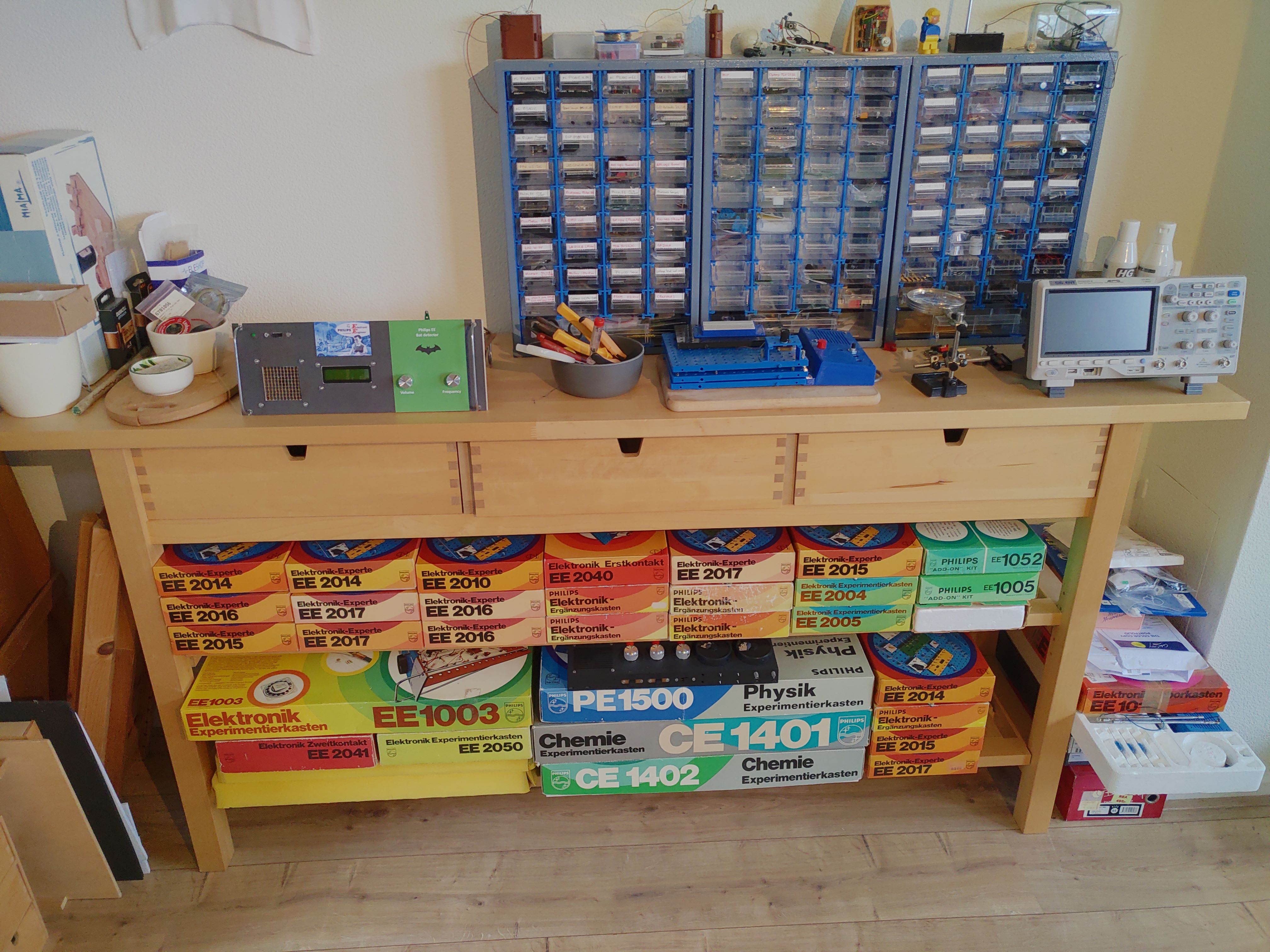
The contributions presented here cover the various projects I have built using the Philips EE system based on the collection I gathered throughout more than twenty years:
The Philiips EE system has been terminated by Philips in 1983, after six generations starting in 1963. It had a recognized place in the larger toy store with a strong pedagogical tone, catering to the serious, technically interested youth in Europe.
Nowadays, with the availability of the Internet in general and specific software tools, it is easier than ever to do prototyping with this system. In particular, there is the availability of the breadboard FIG files, the Philips-EE specific LT-Spice models for use in circuit simulation, the reference websites by Tor Gjerde and Norbert Schneider and of course the Rigert forum with active discussions on both classic and new designs, often with modern components like microcontrollers included. In this way, for active Philips-EE enthousiasts it feels as if Philips secretly never stopped developing, and that we all are the thriving co-designers of this system in these modern times and with a happy future ahead of us!
Here I provide for all design information (electronics diagram, layouts etc.) as well as information on experiences, improvements etc. that may be useful to other enthusiasts of this system. You may click on the title or "read more" to read the full article. Enjoy!
The three-transistor MW receiver (nr. 5.02) has likely been one of the most popular designs in the Philips EE series. This radio was depicted on the boxes of the EE2000 series of kits, it was a very successful design that always worked well and did not need an external antenna. It is a so-called "reflex" design, which means that the first amplifier stage is used for both HF and AF signal amplification, as the rectified signal is fed back to the same amplifier.
Although it is a simple, proven design, I wondered in which ways this beautiful receiver could be improved whilst not comprising its reflex concept. It turned out that there were several opportunities that were discussed with and contributed by the active Philips EE community at rigert.com :
- On component level, here are the "low-hanging fruits" that already improve reception:
- Adding a second rectifier diode (replacing the 10 kOhm resistor) for a stronger overall reception (as the two diodes now work as a voltage doubler).
- Reducing the capacitor in the rectifier circuit for 0.1uF to 22 nf for improved and stronger audio (due to a better RC rectification time constant).
- On board design level:
- Re-arranging the audio section such that the volume control is in between the two audio stages instead of before them, to avoid mechanical noise from the audio potentiometer to be strongly amplified.
- On electrical circuit design level, investigating the following two alternatives (both of which are described in the subsections below):
- Adding regeneration (but that implies an additional control for tuning).
- High-impedance RF-input buffering for improved signal reception, for example using a FET-buffer or a emitter-follower circuit.
- Regarding power consumption, it appears that the standard amplifier stage ("Class A") connecting the loudspeaker consumes a lot of power because of a continuous DC current flow. A Class- AB output ("Push-Pull") is the approach to a much lower power consumption and has been implemented for the regenerative variant of this radio.
Read more: Improving the iconic EE2003 three-transistor (Reflex) MW receiver
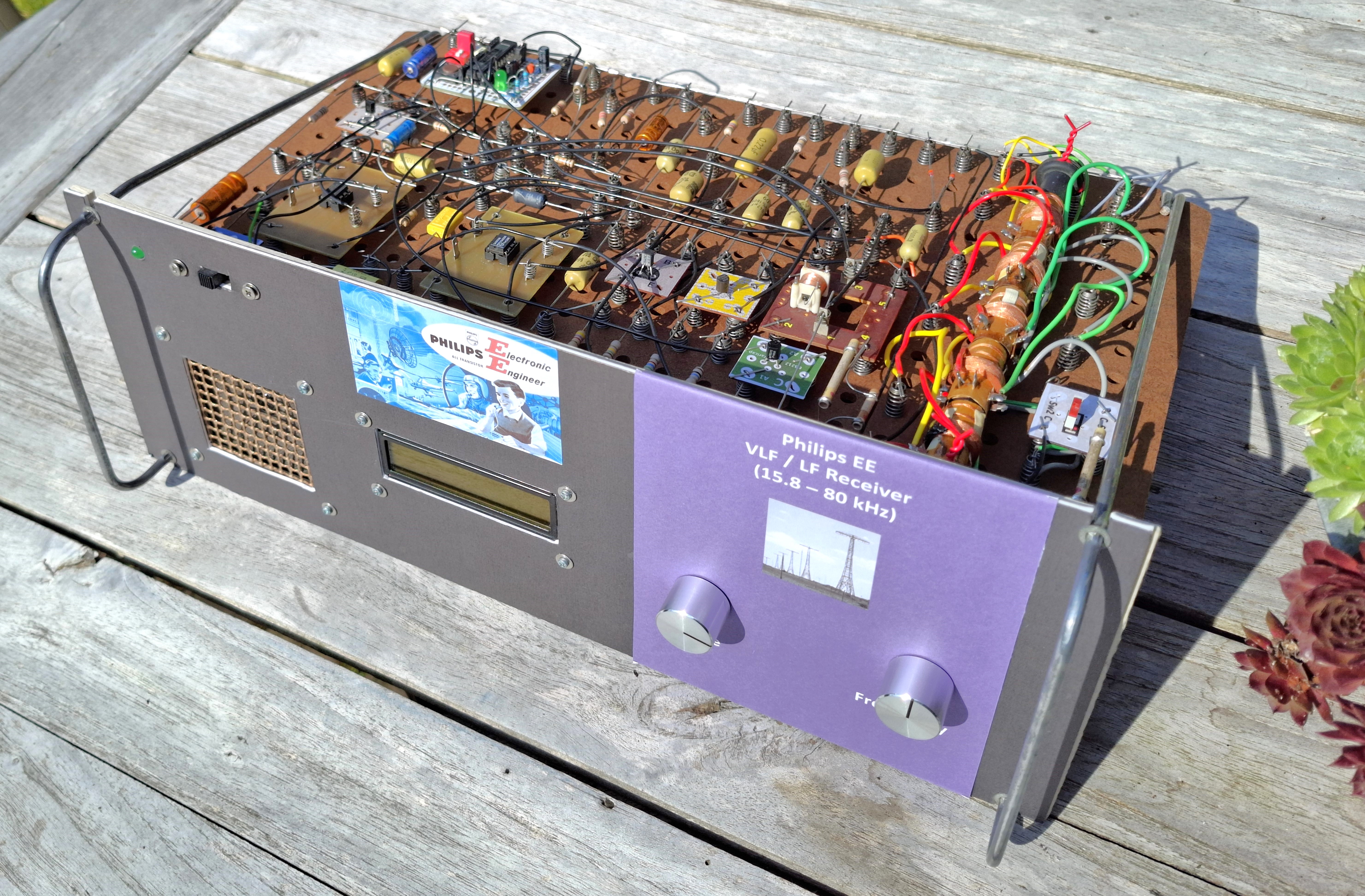
This project started after I read about the Swedish Grimeton/SAQ 17.2kHz telegraphy transmitter station, one of the earliest (from July 1925) but still operational radio stations. Would it be possible to develop a Philips EE design to capture the December 24 2024 transmission at such an extremely low frequency? It quickly came to me that for the VLF band a simple Direct Conversion receiver was possible with the mixing (autodyne) signal being generated by a Picaxe (or any other) microcontroller using a PWM signal. I also had several Longwave coils from a few EE1005/2005 sets available and a 650pF varicap/varactor for AM tuning, so a sensitive tuned ferrite antenna could be possible as well ... .
I just missed the opportunity to have the receiver fully ready at exactly December 24th, but now it is, with the following features:
- Direct Conversion design using the well-known NE602/SA612A mixer chip,
- Five Longwave coils on a series-arranged set of ferrite rods provide 71mH of inductance, allowing a reception range of 16kHz - 80 kHz covering all main VLF stations, like Grimeton/SAQ but also DCF77 at Mainflingen,
- A Picaxe-28X2 microcontroller exerts full control:
- It supplies the autodyne signal via PWM (and a RC-filter) as the mixing frequency, transforming the RF signal directly to audio.
- It controls a band-switch relais to cover the required capacitance range (65pF - 1300pF) in two steps (each band tuned by the same 650pF AM varactor/varicap).
- Tuning of the ferrite loop antenna using the varactor is done per band, directly via the 32-level DAC output of the microcontroller (no buffering needed). Using band-switching, ideally 64 capacitance levels can be provided. Antenna tuning can be done either automatically of manually using the same knob, both modes supported by the LCD interface.
- A mix of components from different Philips EE generations: EE1000, EE2000 and EE2001, plus a few non-Philips EE components.
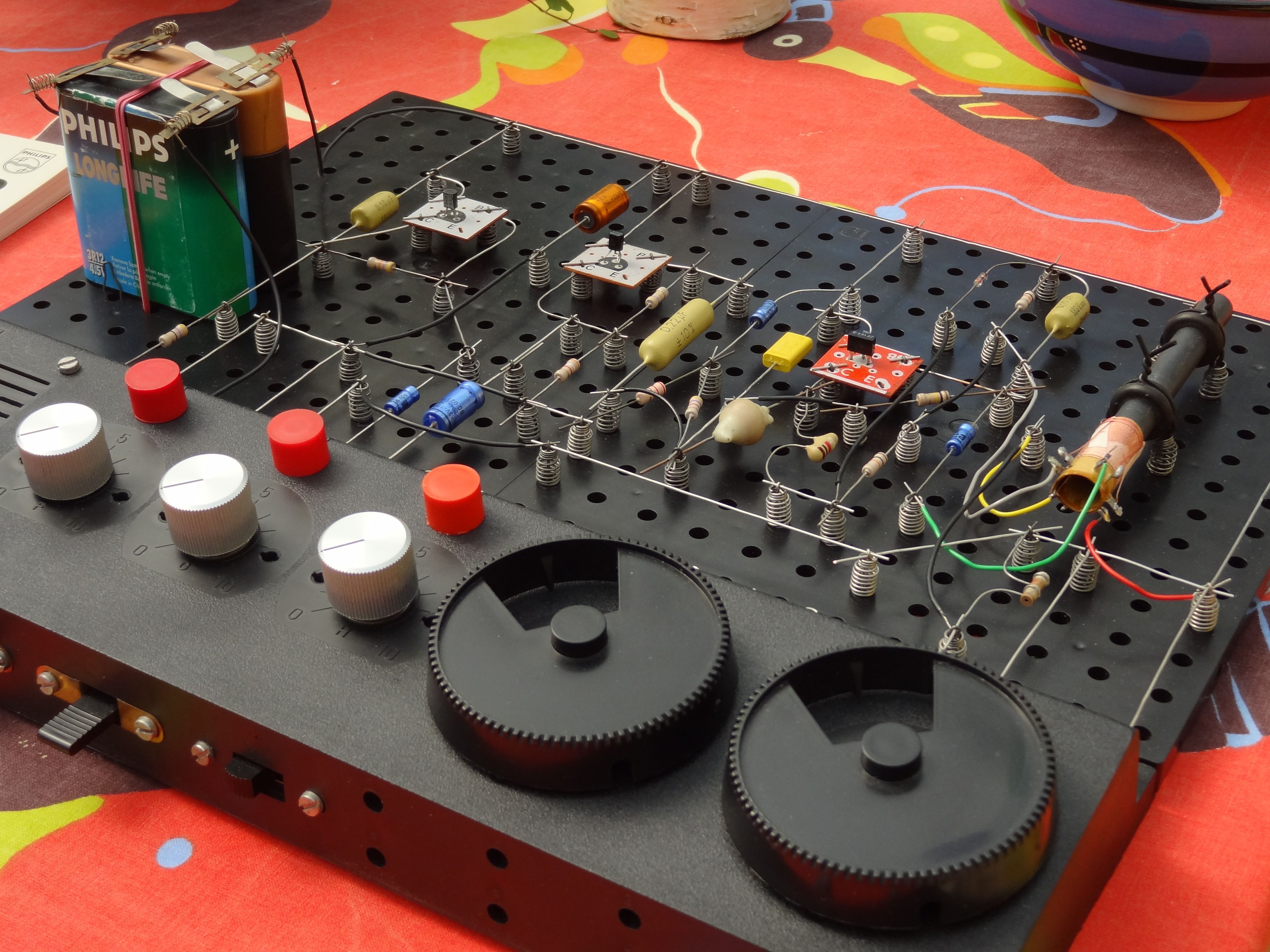
The picture below shows the final hardware setup based on the EE1000 breadboard system which I actually like very much:
Read more: A Philips EE VLF receiver (16 - 80 kHz) with digital control
Although many European and American shortwave (SW) stations have disappeared, there is still quite some activity from more distant, South Asian stations that now have room to be received as well with simple, sensitive receivers.
The EE2003 SW receiver (5.03) can be upgraded towards a more sensitive and controllable design by adding explicit regeneration control outside of the RF-part of the circuit, as I have described here. In that article I show that by controlling the DC Collector-Emitter voltage difference of the RF transistor via the RF-choke using an external potmeter, the receiver can be used to receive both AM stations (at maximum sensitivity just before onset of oscillation) and SSB stations (in oscillating mode, providing the required beat note).
Here follow the key design files for three variants of the same design. The picture here shows the actual layout for the 5.8 - 10 MHz receiver (49m, 41 and 31m bands):
3.5 - 4 MHz (80m):
This design is specifically tailored toward the popular 80m amateur SSB band, with a large coil (29 turns) to increase sensitivity for these low-power stations. In this range, AM stations are basically absent today.
- Picture of the design
- Electrical circuit design (SPlan)
- Electrical circuit design (picture)
- Layout design files:
- Philips EE Layout design (XFig/WinFig)
- Philips EE Layout design (PDF)
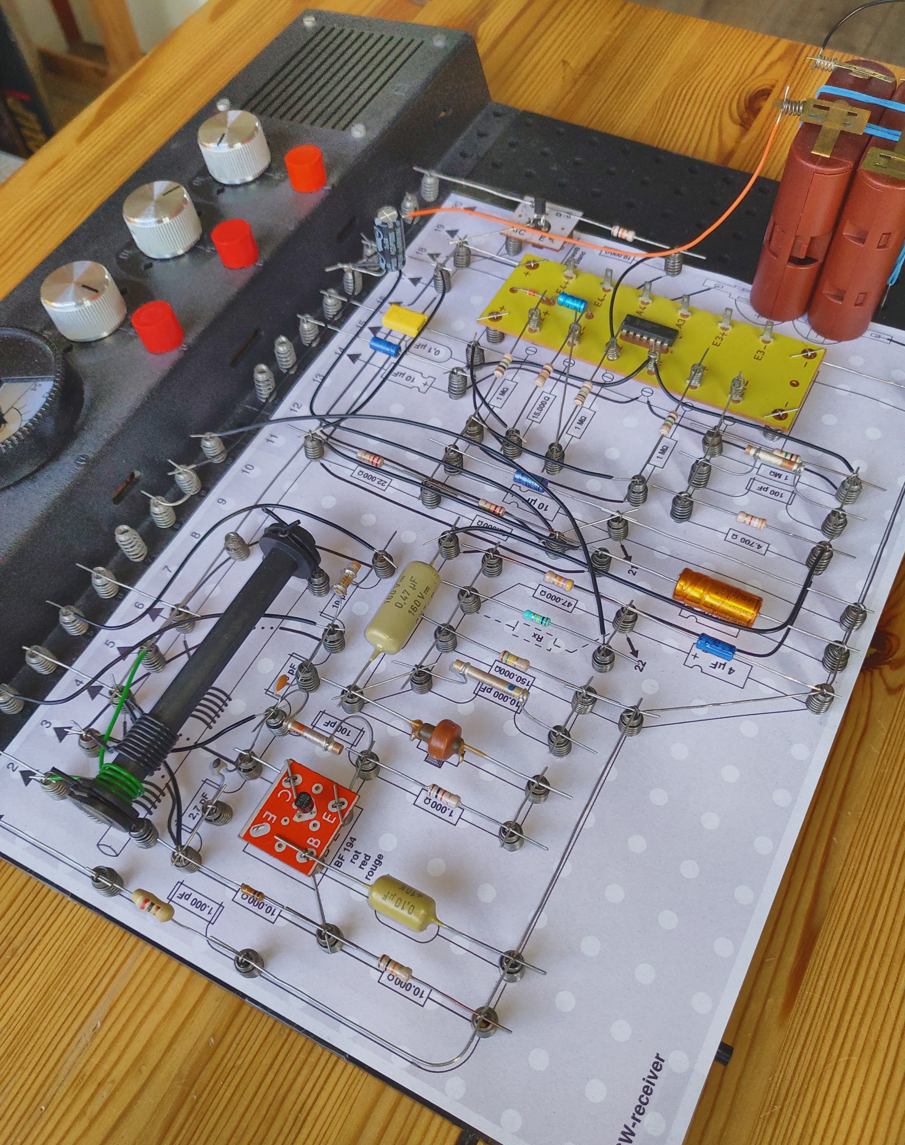
This page describes a powerful MW receiver based on two non-EE components (SA612A mixer+oscillator and MK484 radio ic used as a IF amplifier+detector):
There are a two variants of this design:
- A variant with two red IF coils. This design can be built using a single EE2005/1005 kit , and the SA612A (or SA602A / NE612A / NE602A identical variants) as well as the ZN414 or MK484 AM radio chip
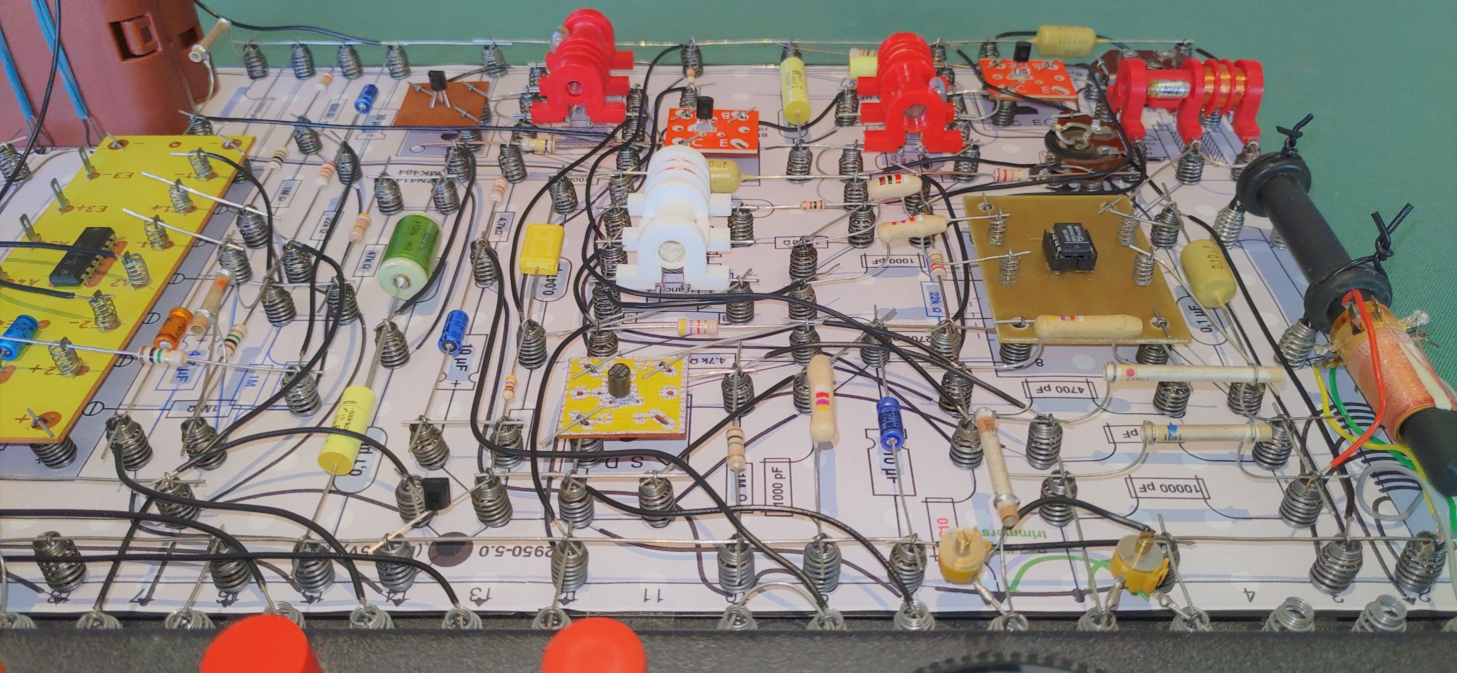
- A variant with three red IF coils (shown in the picture above). This version requires an additional EE2005/1005 kit for the extra IF coil (see Ebay, marktplaats.nl etc.)
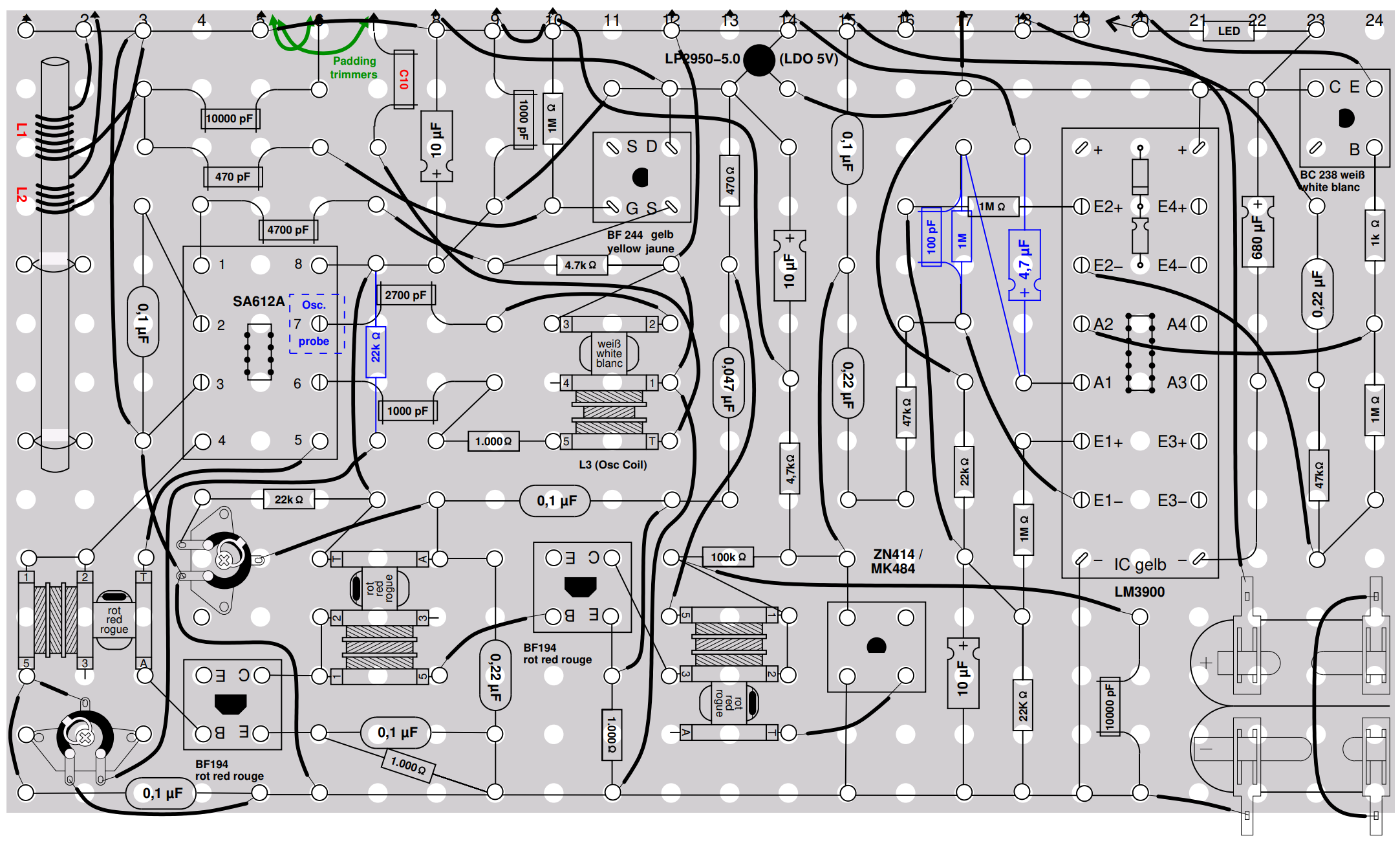
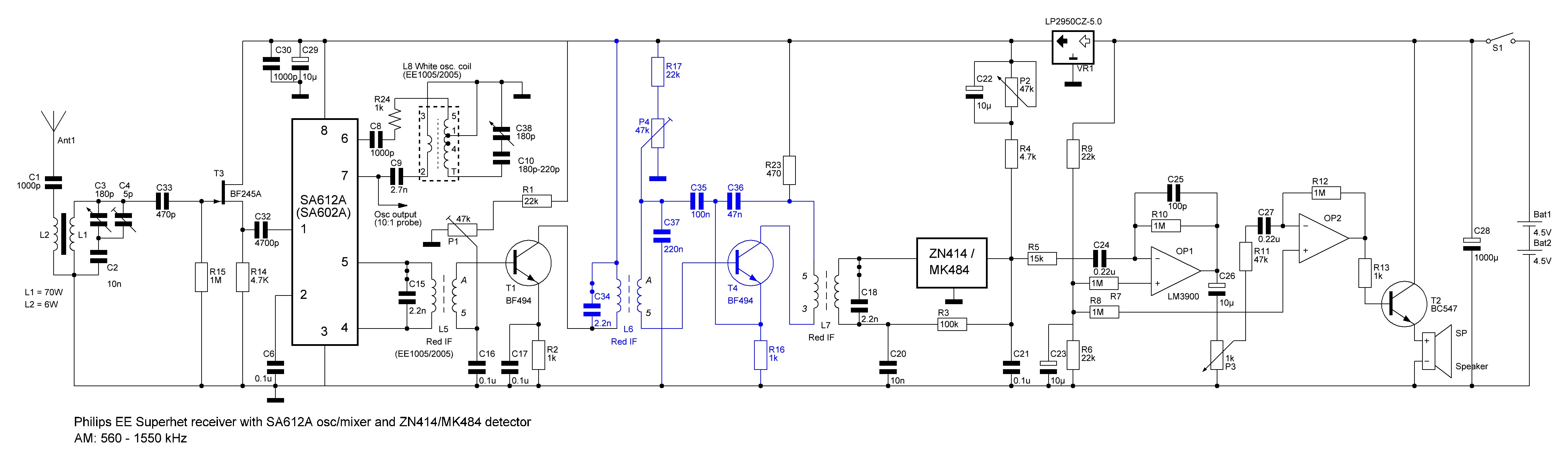
Electrical circuit (describing both design variants) and hints for oscillator matching
The electrical circuit diagram contains the extra IF stage indicated in blue:
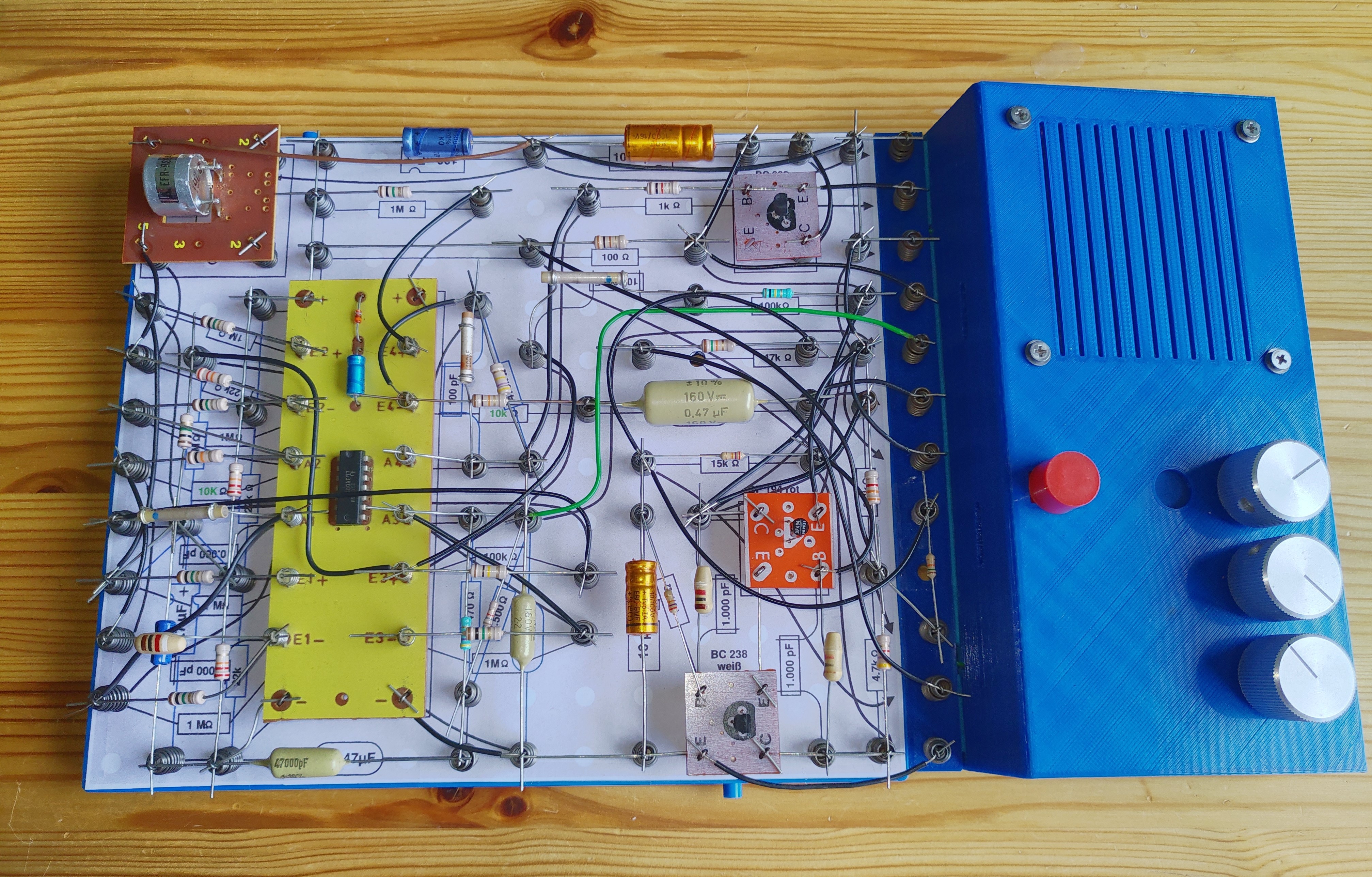
I always wanted to try to get to fit the EE2010/13 FM-receiver with touch controls on a single (14x12) breadboard. And I managed as well:
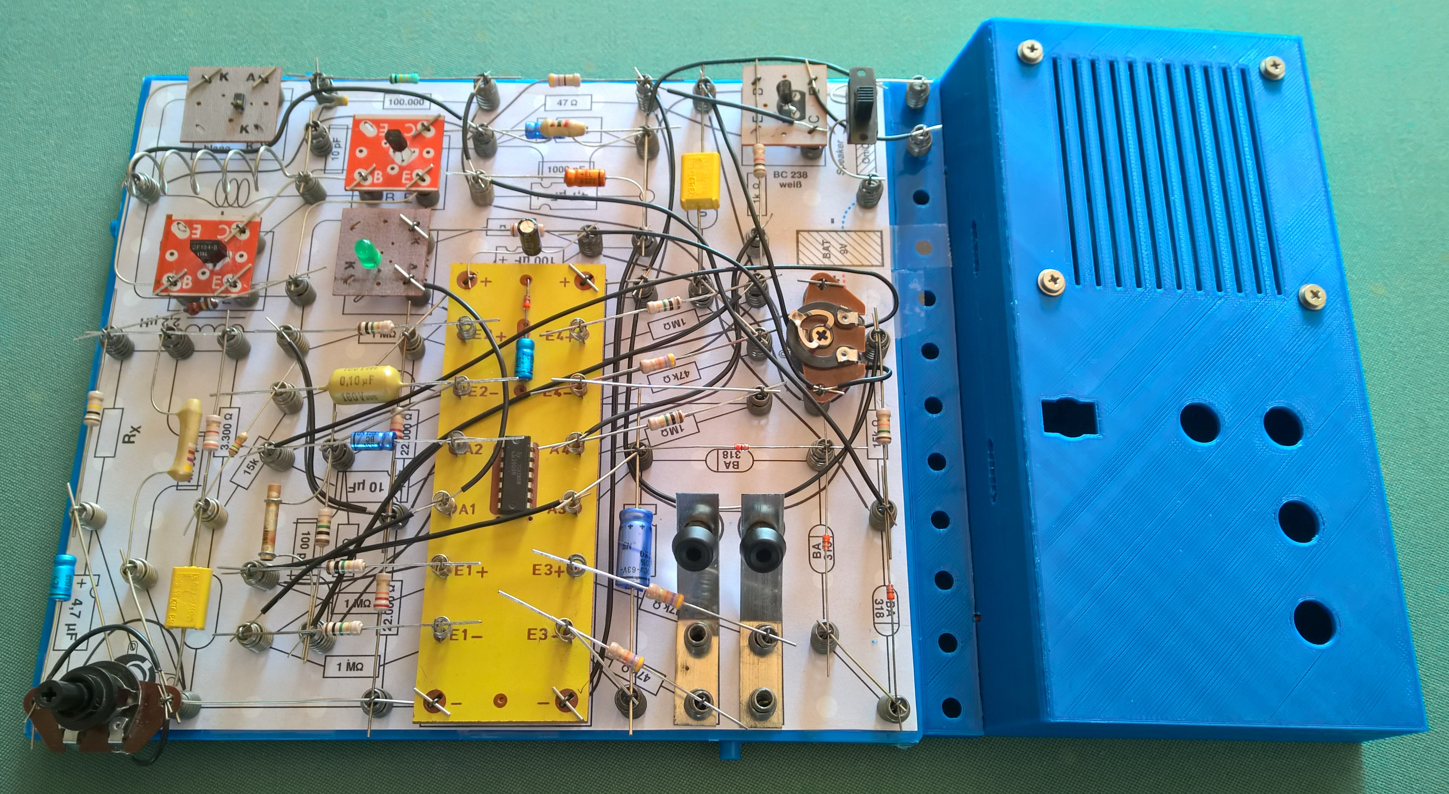
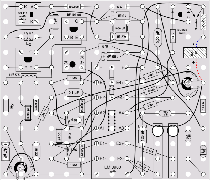
This receiver has both its volume control (potmeter right) as well as the regeneration level (potmeter left) on the board itself, the only external components are the battery connection (with on-off switch) and the loudspeaker. The receiver is tuned (+) (-) by pressing the switches, in idle mode it stays at the selected frequency. This receiver is remarkably sensitive, no antenna is needed.
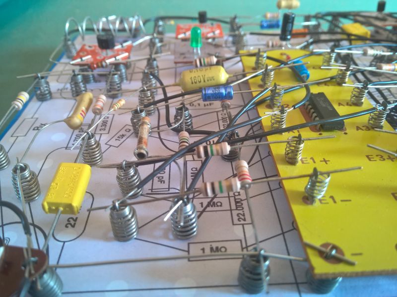
The way to enable this very compact style is to use the fact that the contacts on the yellow LM3900 print are placed somewhat higher than the board spring holding the components. As a consequence it is possible to build at two height levels close to the print, as shown here:
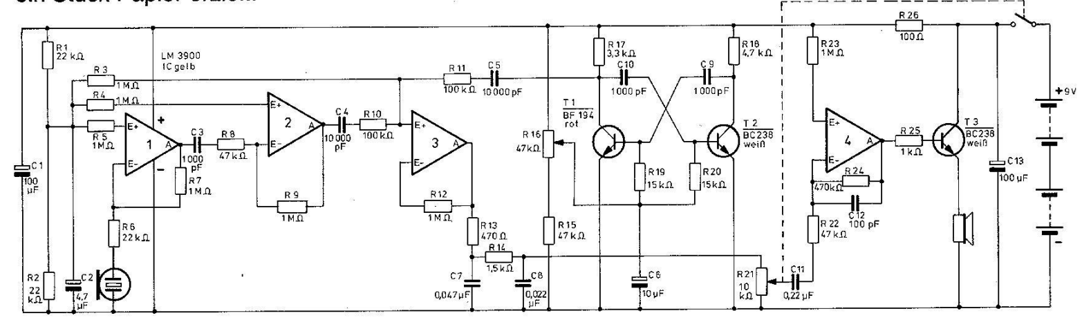
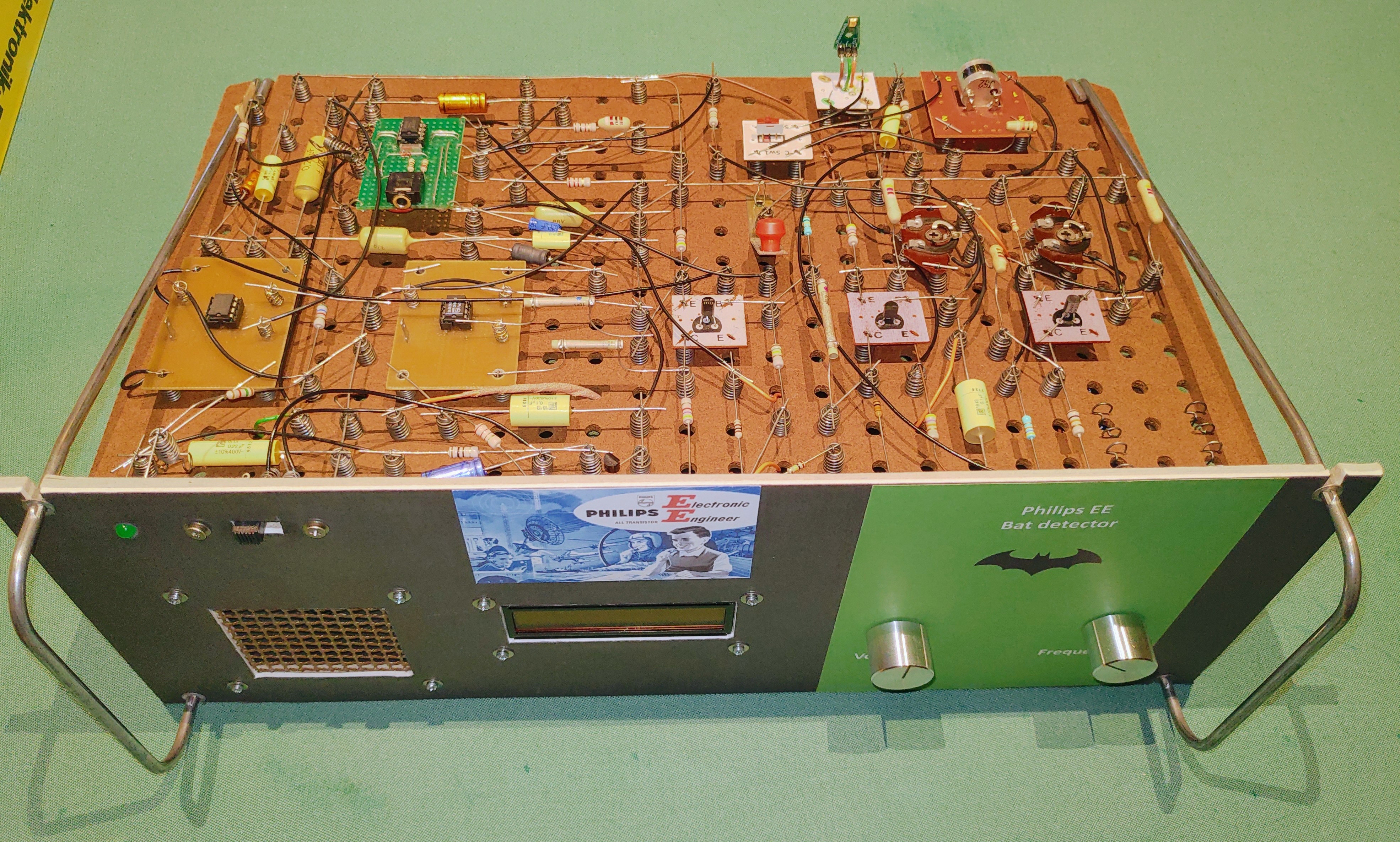
The EE2016 Ultrasonic converter circuit needs only some minor tweaks to turn it into a very useful bat detector. Furthermore, the circuit has several interesting aspects that are not covered in the manual and therefore warrants a separate discussion. The picture below is my implementation and it is discussed here in detail.
This bat detector circuit is based on the original EE2016 4.7.14 circuit ("Ultraschall-Konverter" - Ultrasonic Converter), with the following small but meaningful improvements:
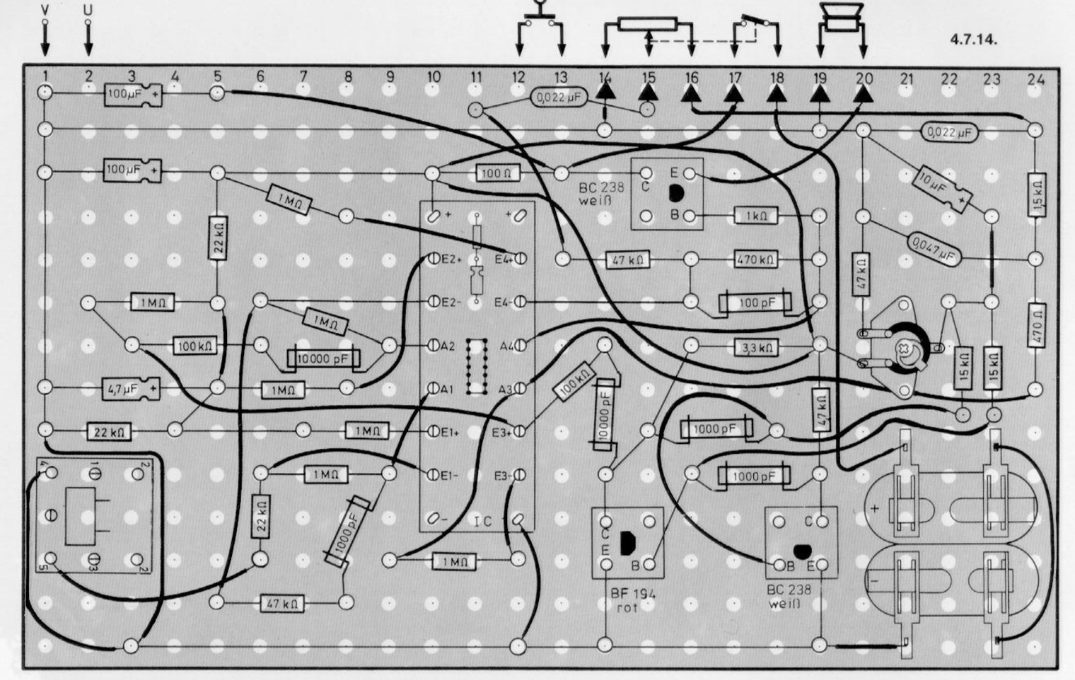
- Compact layout design made for one Philips EE board instead of the original two boards, as shown above
- Improved oscillator circuit (T1/T2),
- Increased sensitivity by reducing a few resistors values, and
- Large capacitor added in the Vcc line for better stability.
The original electronic circuit and component layout in the Philips EE manual are as shown in the figures here below:
The new design appears to work very well: a recording that I made with it is available here: Audio link
It is based on the following improvements:
Read more: EE2016 Ultrasonic converter revisited and improved - Heterodyne Bat detector
Although the EE2016 ultrasonic bat detector as published on this website works quite well (using the kit's 40kHz transducers), I felt there was potential to improve on both sensitivity, frequency range and functionality. Since I am fond of using the SA612A (NE602A) mixer chip (see the superhet radio), I stumbled upon Bertrik Sikken's analog design for a bat detector and extended it with a broad-range MEMS-microphone (20 - 120kHz), a different audio circuit (based on the TDA7052A) and a microcontroller (PICAXE-08M2) to allow for a LCD/OLED display and an automatic frequency sweeping mode. The initial setup is shown here, which reveals that another goal was to see how designing my own front panel for the EE1000 works out in practice:
The resulting device is actually performing very well, also through the help of many contributors (see links below) and I can really recommend building it (but then please check these links). Note that one can easily exchange the audio circuit and the microcontroller type with another one that suits better.
Here follows more information on the latest versions of the design and the discussion links:
Electrical Circuit Diagram and required microcontroller software to have it operational:
- Electrical circuit design (Splan)
- Electrical circuit design (picture)
- Microcontroller (PICAXE-08M2) software (Picaxe BASIC)

Read more: Another Bat Detector (more advanced and sensitive) with frequency sweep control
LT-Spice is a commonly accepted tool for doing circuit analysis. Since Philips EE components like transistors, diodes and chips are quite mature (and in earlier EE-kits these components are ... old), they are often not represented in the standard LT-Spice component library. Furthermore, their behavior may differ from their default LT-Spice counterpart. For example, the LM3900 is a current-differencing "Norton" amplifier that works quite differently from a standard voltage-differencing OpAmp, even though the type of applications is very similar.
Therefore it is valuable to have a collection of Philips EE-specific component definitions. Based on some searching and inquiries (and calculations for some varicaps) it was possible to compile a list (v1.5) of most of the relevant types:
- Diodes and varicaps/varactors: OA91, OA95, BA318, BB110, BB109, BB209, BB112, BB212
- Transistors: BF494, BF495, BC547A, (BF547B, BC547C), BC548A, BC549B, BC549C, BC550C, BC557C, BC559B, BC559C and BC560C
- FET's (JFET): BF244A, BF245A/B/C, J201
- IC: LM3900 (component definition and Norton symbol-specific graphical layout, in two separate files). It needs to be noted that the source of this excellent model is Mr. Helmut Sennewald, see this link for background information.
- MOSFETs (not part of any kit, but handy though): BSN254A, BS107, (BS170)
In order to use them, the following steps are advised:
Firstly, the following files need to be downloaded ("Save link as") in your local simulation directory (i.e. your active working directory where your application is located):
- Diodes, transistors and FETs: Philips_EE.txt
- LM3900: LM3900 Model (MOD) file & LM3900 LTSpice Symbol (ASY) File
Then, in your application in LT-Spice do the following:
- Add the following SPICE directive (button in main menu): .include Philips_EE.txt
- For diodes, transistors and FET's: select the standard component, add it to your design, then edit the component name. It will then be automatically recognized from the Philips_EE list
- For the LM3900: press the Component button, in the window that opens select at the top your active working directory (and the LM3900 MOD and ASY files should reside there as well), the LM3900 symbol should then show up and can be selected.
As a test example, the following model of a LM3900-based VCO (derived from AN-52) should be able to run directly in LT-Spice (and to test it: check different values for V2 and then see how the frequency at the Opamp's outputs changes):

As a final remark: Note that a few more archaic components are not in the list, I am happy to be informed about contributions!
The Push-Pull circuit for the final loudspeaker amplifier stage as proposed by Sven @ Rigert Forum provides several important advantages. He particularly confirms the following ones:
- Significantly lower power consumption,
- Higher volume (at a given power consumption level),
- Less distortion.
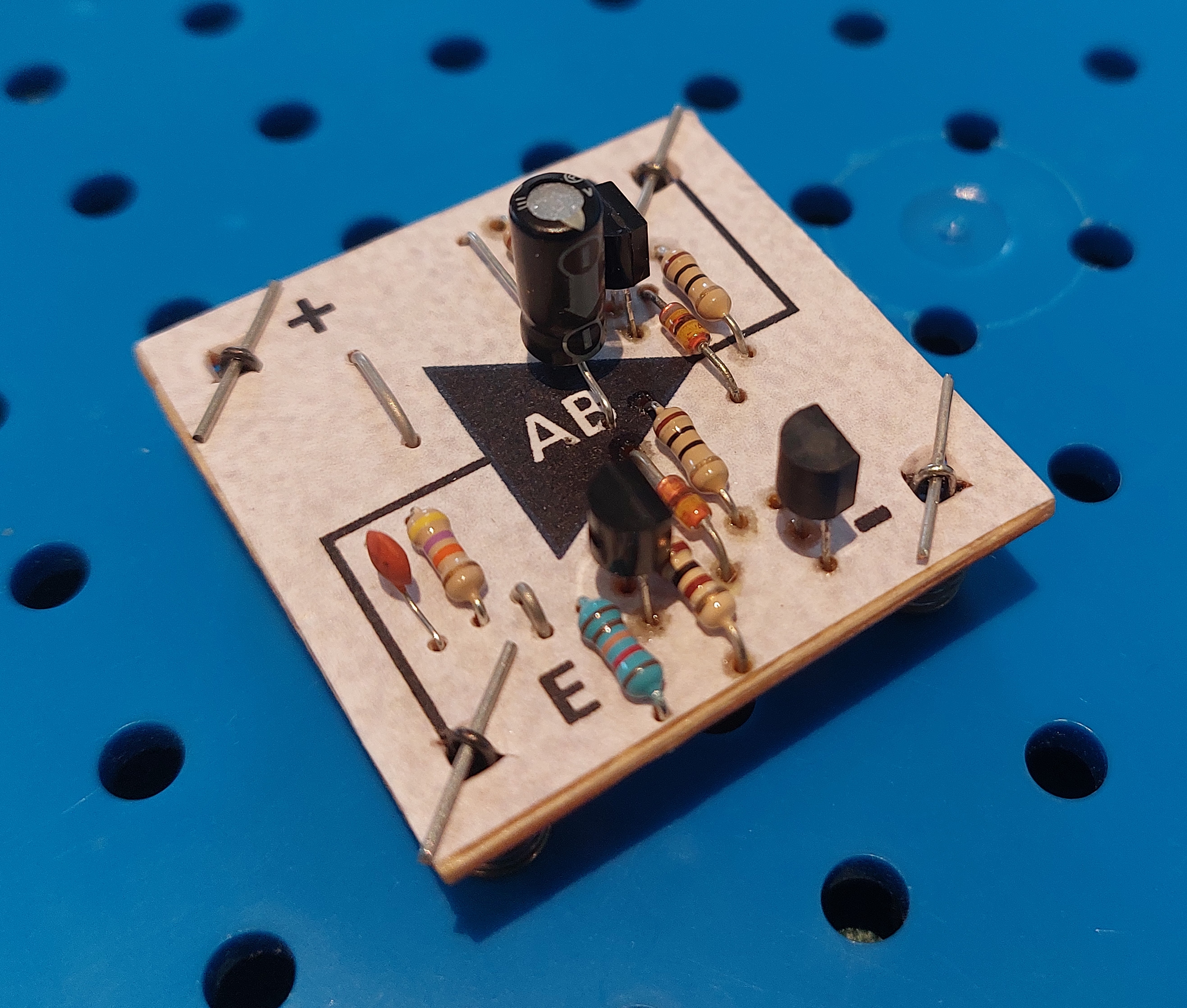
Since these are very important characteristics, I built the circuit myself as well and could confirm these properties. Thus, I decided to design a small 3x3 circuit board to contain the whole circuit so that it could replace the standard BC238 transistor audio end-stage, including feedback resistor and coupling capacitor. As a consequence, some extra advantages emerge:
- Less Philips EE board space required as compared to the original audio end stage,
- Allows any speaker with an impedance of 8 Ohm of higher to be used, so the audio transformer in the later versions of EE2000 and in the EE3000 series is not required anymore,
- It can be used directly in both EE1000/2000 and EE2001 series.
which makes this a highly recommended application. Here below follows all design data needed to make your own board from standard stripboard material:
A picture of the design (an slightly earlier version lacking the decoupling input capacitor):
Read more: A compact Push-Pull audio amplifier component board
Tor Gjerde has published his *.fig templates (based on the XFig vector drawing program) for generating breadboard layout files. I have used them extensively to give my projects that official Philips EE look that is virtually indistinguishable from the original Philips EE versions.

His templates are published on his website: Link Tor Gjerde . These published templates as well as his EE2003 diagrams are in XFig Metric size units (not Imperial). He appears to use the XFig for creating his diagrams, not the more modern WinFIG - which I use.
Regarding WinFIG (MS-Windows) - XFig (Linux) interoperability of files it appears that the use of the Imperial instead of Metric units has the advantage of giving exactly the same results on printing, whereas in Metric format a correction is needed when WinFig is used. The background is explained by the author of WinFIG (Andreas Schmidt) in detail on his FAQ page under the section "Drawings that were created with Xfig using metric units (cm) are slightly smaller in WinFIG". As a conclusion he states: "You can avoid all that trouble by using imperial units only".
Therefore, here follow the links to the Imperial versions of Tor Gjerde's template files (which he does not publish in the mentioned link but which I received from him):
- Grid with battery and numbered external connection positions
- Various components (including trimming potentiometer and Push-Pull ("Class AB") board)
- Transistors in various orientations
- Resistors in various orientations
- Capacitors in various orientations
- Coils in various orientations
- Trimming potentiometer (is now part of the "Various components" file)
- ICs from the EE 2001 series (including an extra DIP8 variant)
Read more: WinFIG - XFig layout files: Maintaining Interoperability, PDF generation and printing
The panel design of the capacitance knobs can be redesigned by using the following MS-PowerPoint template (print to scale): PPT-link
The template provide for the design of scales that look as follows:
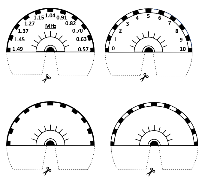
In practice this template may be used to give a lighted scale as shown here (in this case using LED's in E10 fittings, see discussion below):

The background lighting can be arranged as intended and described in the Philips EE manuals, but the Philips kits contain classical lamp bulbs in E10 fitting which consume a lot of power. Luckily, there is source of LED-based bulbs in E10-compatible fittings (they look as a classical bulb, with a classical LED mounted inside), and I have used them as shown in the picture above. I can really recommend their use as their power consumption is only a fraction of the original lamps, and they emit a very natural-yellowish warm light color that resembles their original counterpart very well. The LED's can be used without a resistor up to 4.5V, for 9V use (like in all E1000/2000 circuits) a series resistor of at least 470 Ohms should be used, and in practice 1k appears more than sufficient (with a resulting current consumption less than 2mA). More info on my experiments with them can be found here: link
As your Philips EE system starts to age, this often becomes apparent through the following two symptoms:
- The transistor PCB's are getting to look worn down
- you wish to use more modern and very useful components, like LDO's, the ZN414 / MK484 radio chip etc. etc. .
In those cases you may want to make these components mechanically suitable and having the appearance (again) of a new Philips EE component. For that reason I developed a MS-PowerPoint file with templates for stickers with the following very typical Philips EE look:
![]()
Please feel free to download the PPT file below and make your own adaptations as you see fit. The file contains also a few hints on how to print properly (scaling need, type of sticker paper etc.). Apart from a pair of scissors, a small, very sharp cutting knife is useful here too ... .
Note: The current file is extend it with more designs, including those for the standard Philips EE transistors and varicap.
Link to the file: Philips EE Sticker PPT
As a first step before soldering components , a fixative layer has to be sprayed (in several steps) to protect the printed layer from being damaged by the heat of soldering components (as I experienced myself) and also to protect in use. For this I have used an acrylate-based spray used for protecting sensitive artwork called "Fixatief" from Van Beek Artsupplies. I applied it six times in total, with a 15 mins drying period in between. In the process I covered a few critical components (LEDs, etc) with a tissue/foam to avoid it being in contact with the spray.
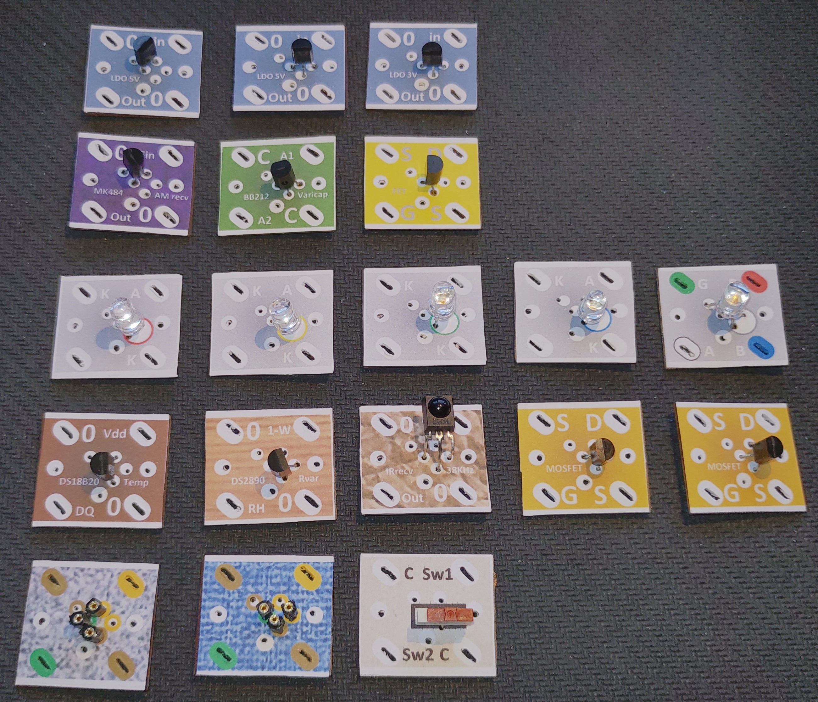
Here follows an impression of my application of the stickers, mainly to integrate new components in the Philips EE system as "lookalikes", showing that this works really well.
In the picture below, most of my updates are shown:
Read more: Defining your own stickers for transistors & IC boards
The following pages contain a lot of information on the EE2000/EE2001 series, including new designs, adaptations of existing designs, as well as error corrections: http://www.kranenborg.org/ee