This project started after I read about the Swedish Grimeton/SAQ 17.2kHz telegraphy transmitter station, one of the earliest (from July 1925) but still operational radio stations. Would it be possible to develop a Philips EE design to capture the December 24 2024 transmission at such an extremely low frequency? It quickly came to me that for the VLF band a simple Direct Conversion receiver was possible with the mixing (autodyne) signal being generated by a Picaxe (or any other) microcontroller using a PWM signal. I also had several Longwave coils from a few EE1005/2005 sets available and a 650pF varicap/varactor for AM tuning, so a sensitive tuned ferrite antenna could be possible as well ... .
I just missed the opportunity to have the receiver fully ready at exactly December 24th, but now it is, with the following features:
- Direct Conversion design using the well-known NE602/SA612A mixer chip,
- Five Longwave coils on a series-arranged set of ferrite rods provide 71mH of inductance, allowing a reception range of 16kHz - 80 kHz covering all main VLF stations, like Grimeton/SAQ but also DCF77 at Mainflingen,
- A Picaxe-28X2 microcontroller exerts full control:
- It supplies the autodyne signal via PWM (and a RC-filter) as the mixing frequency, transforming the RF signal directly to audio.
- It controls a band-switch relais to cover the required capacitance range (65pF - 1300pF) in two steps (each band tuned by the same 650pF AM varactor/varicap).
- Tuning of the ferrite loop antenna using the varactor is done per band, directly via the 32-level DAC output of the microcontroller (no buffering needed). Using band-switching, ideally 64 capacitance levels can be provided. Antenna tuning can be done either automatically of manually using the same knob, both modes supported by the LCD interface.
- A mix of components from different Philips EE generations: EE1000, EE2000 and EE2001, plus a few non-Philips EE components.
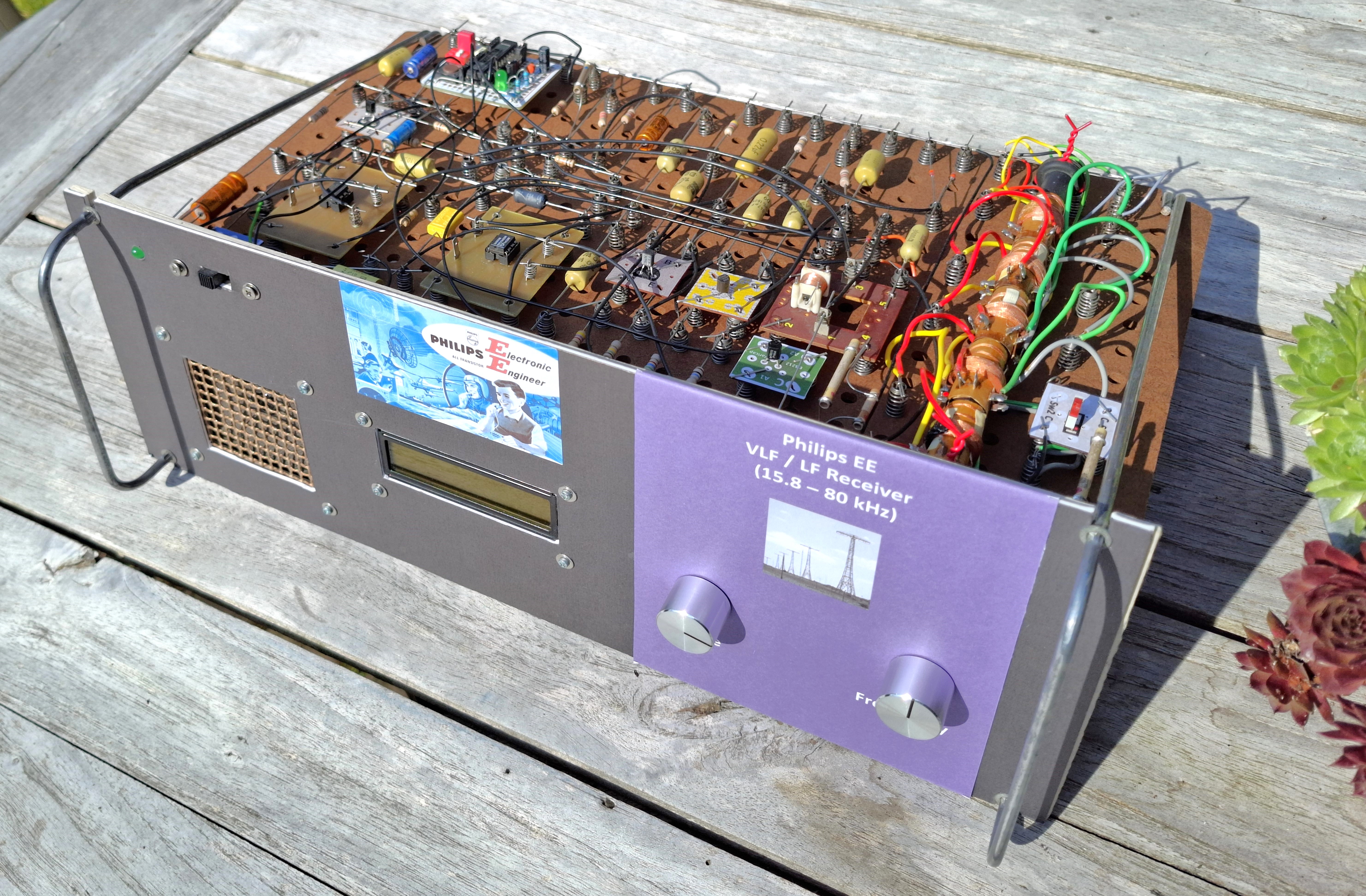
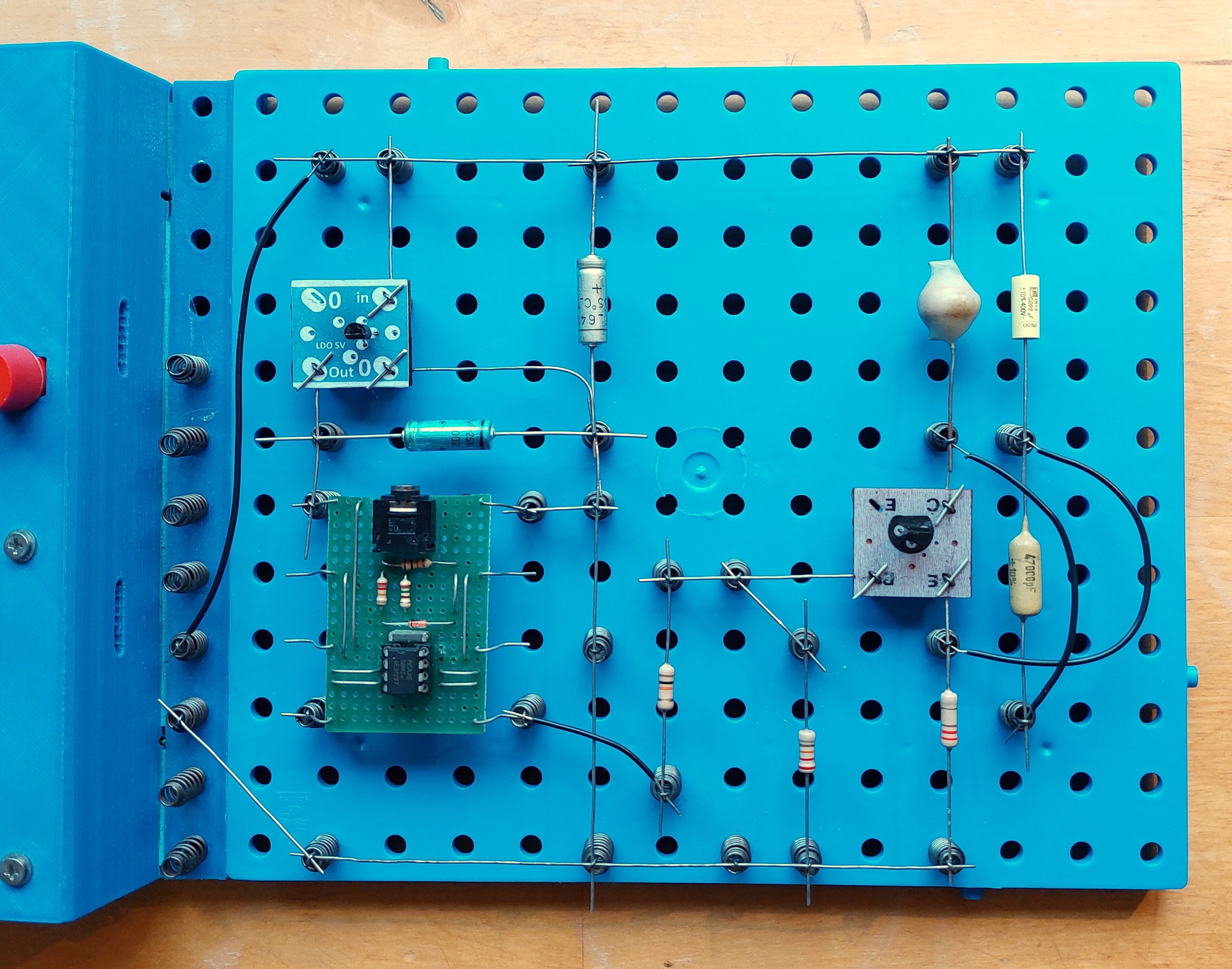
The picture below shows the final hardware setup based on the EE1000 breadboard system which I actually like very much:

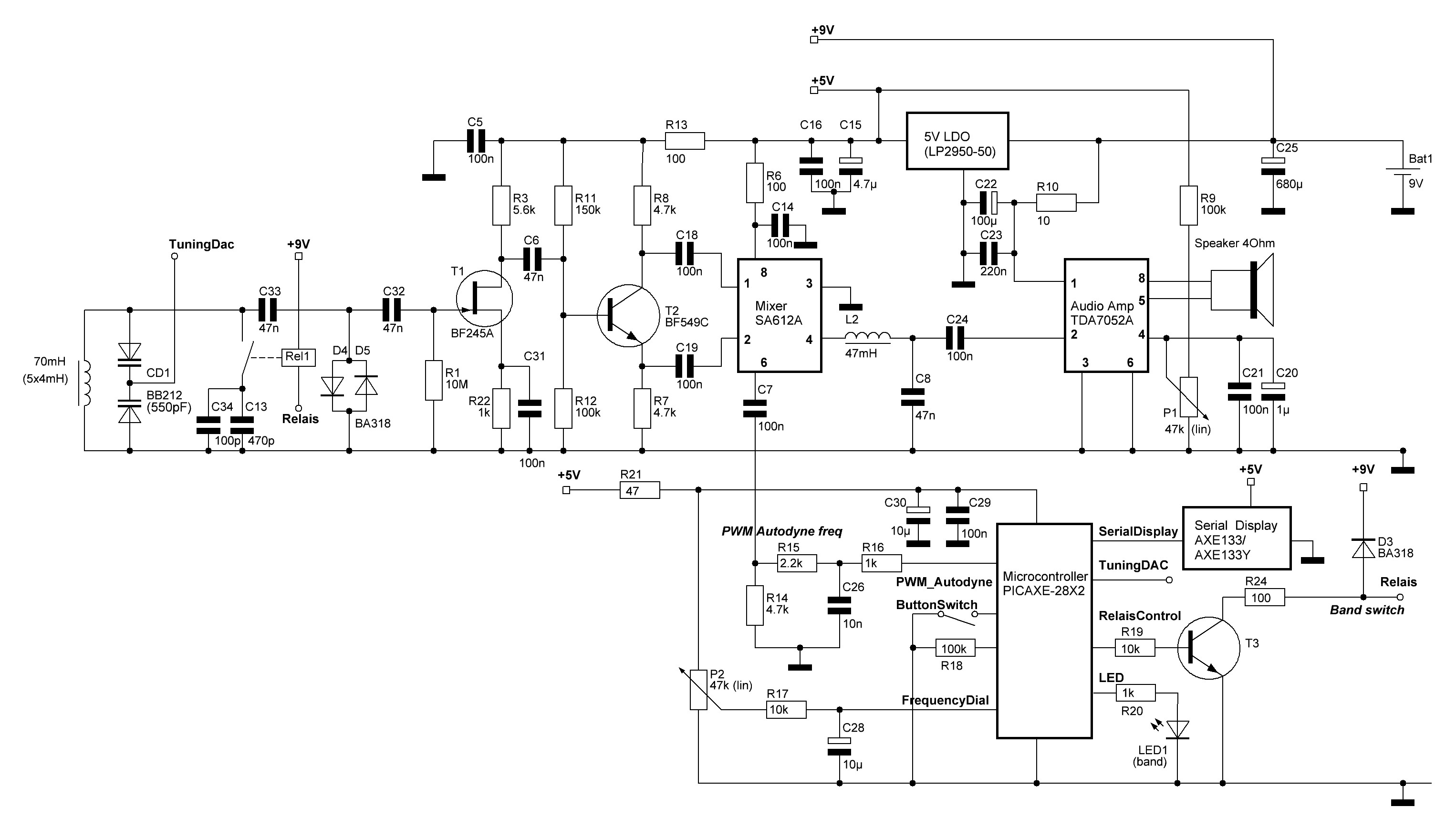
The architecture of the DC (Direct Conversion) receiver shows the role of the Picaxe microcontroller:

The microcontroller:
- Generates the baseline frequency (16kHz - 80kHz) for the mixer/downconverter using a PWM signal and subsequent RC-filtering. In this low frequency area the frequency step size of the PWM (8-bit resolution) is sufficiently small to be applied here (min. 400Hz, max. 1600Hz).
- Tunes the VLF ferrite coil using the varactor/varicap close to the PWM frequency in order to optimize signal reception. The DAC signal output can be applied directly to the varactor.
- Switches a relais, as two frequency bands are required in the current setup to cover the 65pF - 1300pF capacitance range needed for the full 16kHz - 80kHz reception range.
Below is a picture of the detailed electronic design:
Here is the latest version (V2) of the software (Picaxe BASIC) for the controller that makes the radio actually work (it includes test programs for the HW-modules as well): VLF-Receiver.bas. This version includes the manual antenna finetuning option, allowing the varactor capacitance to be varied. The pictures below shows the two modes (Receiver and Antenna Tuning) work out in practice. In both modes the same dial is used:


The below pictures give a nice overview of the kind of components used:
First of all: in the final design yet another LW-coil needed to be added (the last one I still had left, really ...) for a total of five coils, increasing the total coil inductance from 52mH to 71mH. The required capacitance range (56pf - 1300pF) for the 80kHz - 15.8kHz range can then be managed with band-switching between just two bands requiring only one relais:
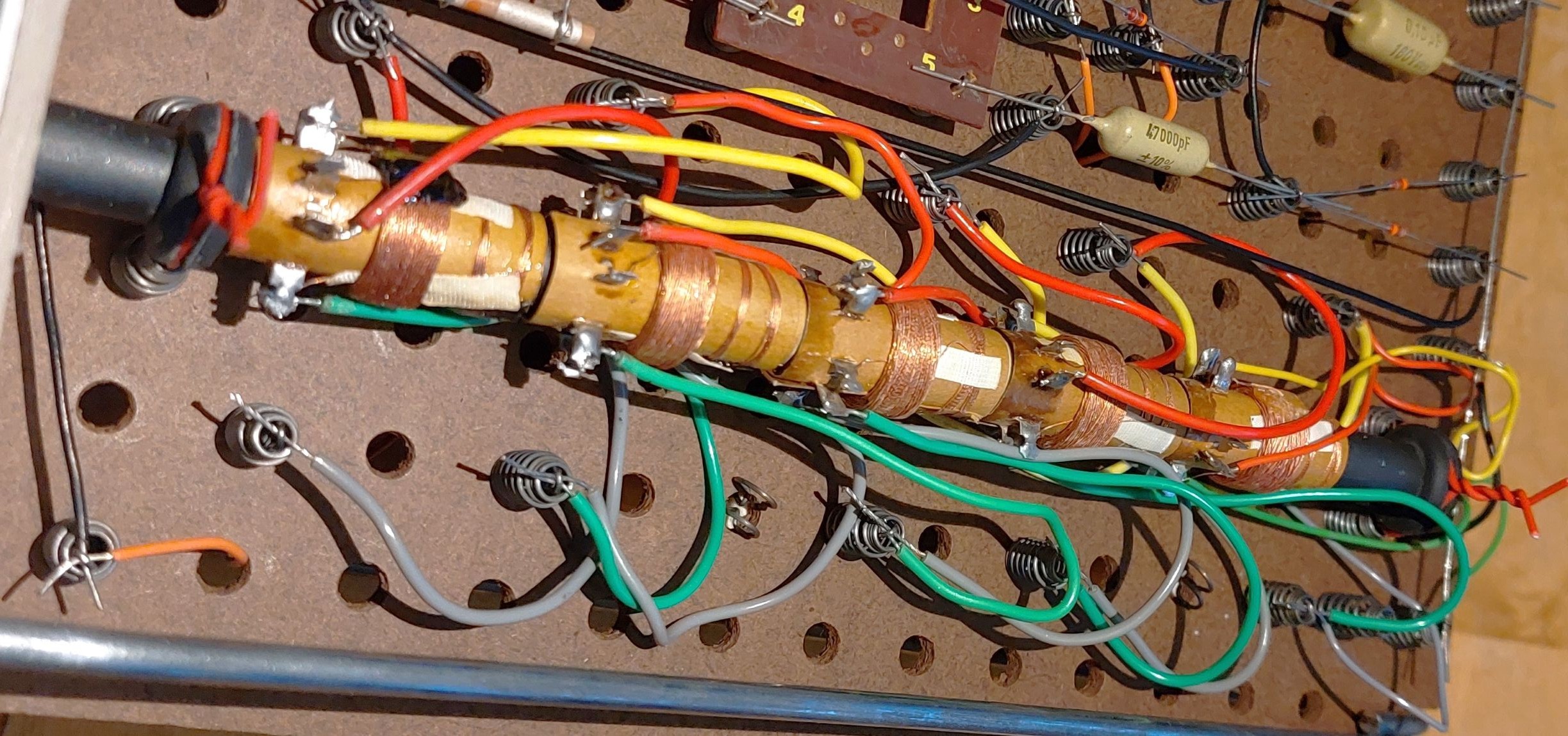
The picture below indicates the kind of components used. Note the mustard capacitors and the tube capacitor typical of the the earlier ('60 and '70) Philips series. The relais and the yellow FET are both from the latest (EE2001) series:

Another picture shows the green varactor component in more detail. It is not a standard Philips EE component, I created it myself using the sticker set on this website. The brown IC component at the right (the SA612A RF mixer) is a home-made board variant as well.

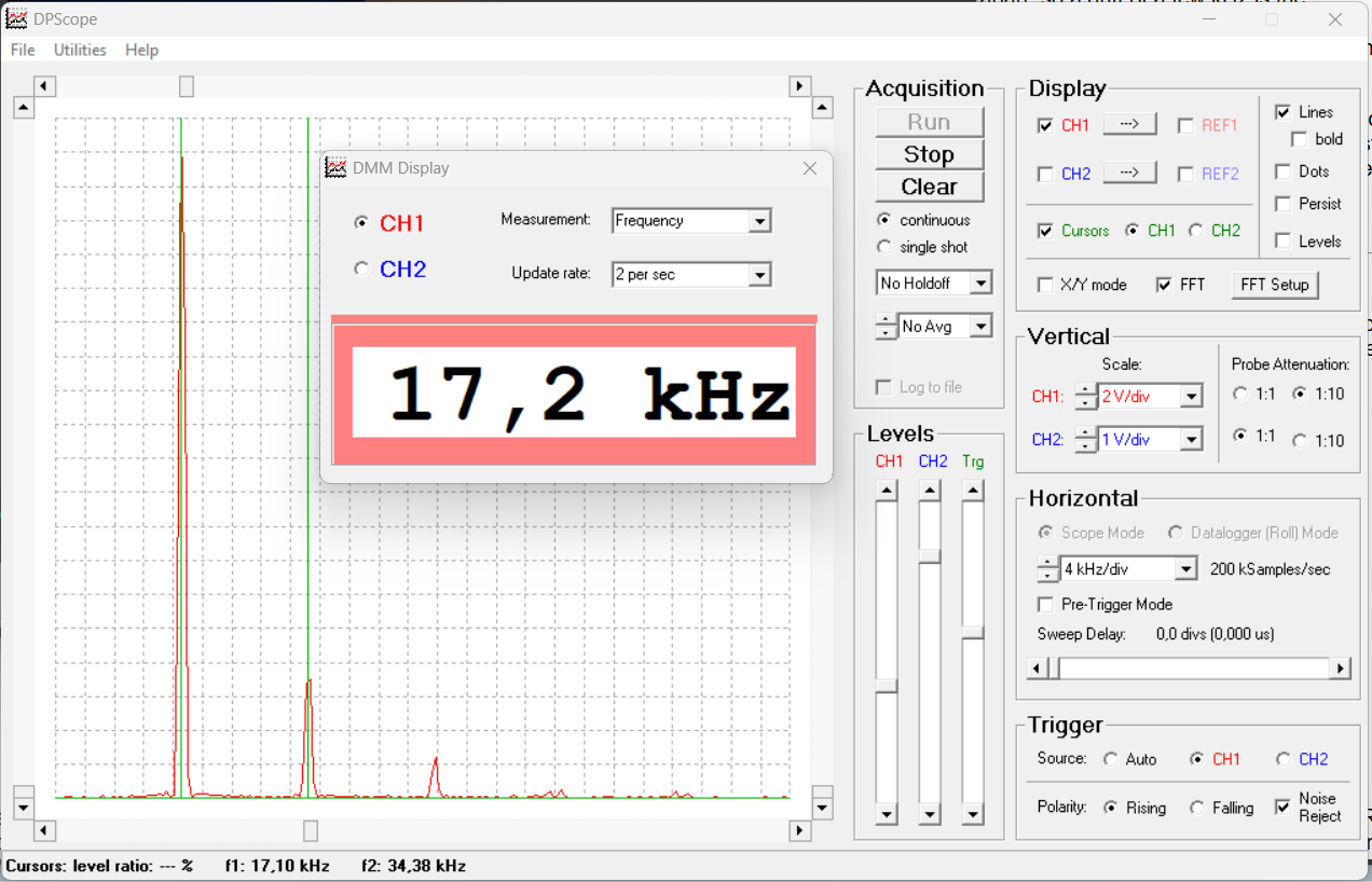
Here are some examples of signals in the VLF band, as recorded from this receiver:
- Sound recording of DCF77 time signal (77.5 kHz), including the 1-minute marker
- Sound recording of the DHO38 submarine communication FSK signal (23.4 kHz)
Testing & optimization for Grimeton/SAQ at 17.2 kHz:
In order to generate a test signal at 17.2 kHz, a classical simple LC-circuit from the EE2003 manual can be adapted easily:
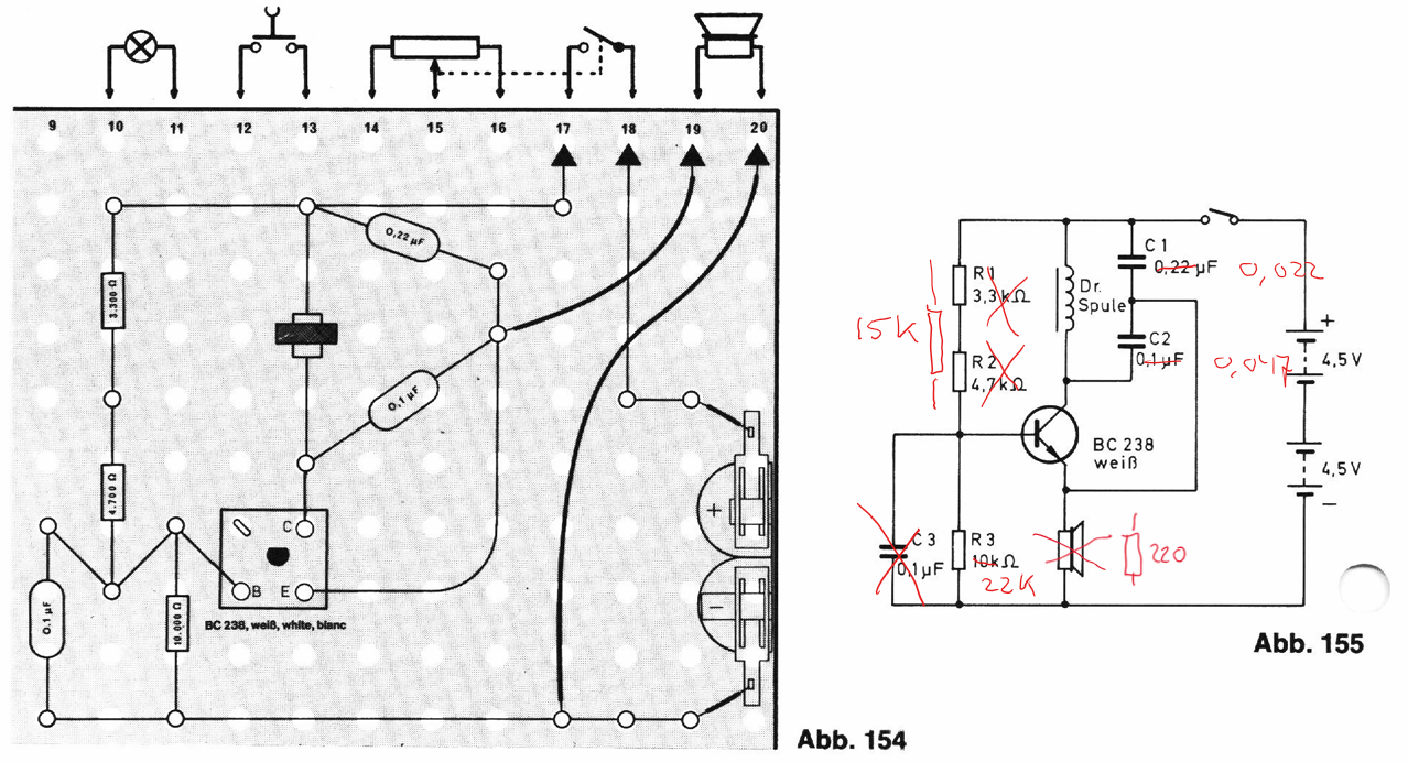
The harmonics of this test transmitter can be used to investigate the fine-tuning of the antenna resonant circuit:
Lastly: by having this small transmitter controlled by a simple microcontroller (switching the oscillator on/off by setting the base voltage of the transistor) a CW-modulated version is possible, leaving its signal easy to discern from the many other signals that are present:
This project benefitted greatly from the discussions on rigert.com and sparked a discussion over there on how an existing Philips EE design (7.02, TV-Set Detector / Peilgerät für Fernsehempfänger) could be directly suitable or even optimized for Grimeton/SAQ as well!