PICAXE™ "SerialPower I & II" Network
"Combining power delivery and
bi-directional communications between intelligent nodes
using just two interchangeable wires"
SerialPower 1 v4.0 for Picaxe M2/X2 - simple fixed 2-byte data format
(September 2018)
SerialPower II for Picaxe M2/X2 - flexible 1- to 32-byte data format
(November 2022)
(Note: Version 3.0 for older Picaxe M/X variants still accessible here, functional but not maintained anymore)
Summary
The Picaxe "SerialPower" Network combines power delivery and
bi-directional communications between processes on intelligent nodes. This can be implemented
using just two interchangeable wires. Simple diode-mixing networks with separate power and communication wires are supported as well. The network allows messaging between a node and any other node(s), allowing the implementation of truly distributed systems.
Principles
This network is based on two concepts:
- Networking hardware for linking Picaxe-based nodes.
- Picaxe network software that implements communicating processes in a highly automated fashion.
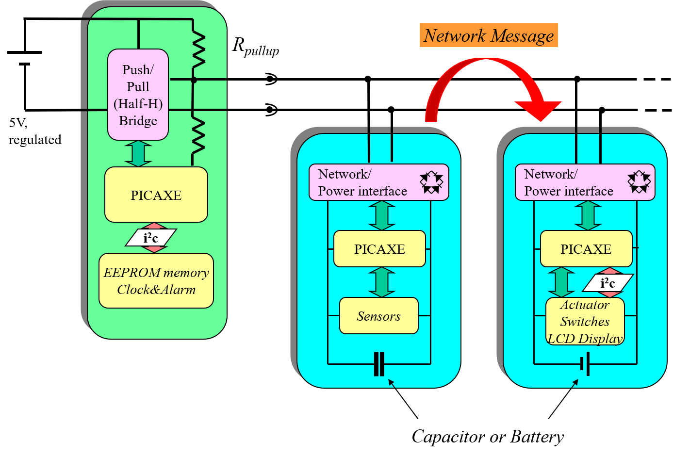
A master node (Picaxe 08M2) provides for power as well as "timeslots" during which processes on nodes can exchange messages with each other using a standard format 4-byte format for 2 byte data (for SerialPower I) or a more flexible 1-32 byte data format (for SerialPower II):

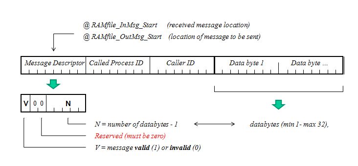
Each process has a unique ID, and each timeslot includes the ID of the process that is allowed to use it for putting its message on the network. The slave nodes are powered from the network and only need a backup capacitor (which may be replaced by a local power source). These nodes can be implemented using any available Picaxe type (M2 and/or X2).
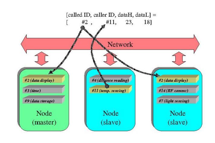
The concept of communicating processes is used, allowing abstraction from physical nodes and thereby flexible distribution of functionality over different nodes. A node may implement several processes, and the same process may run concurrently on several nodes with local modifications.
Almost all of the network operation and message assembling is done automatically.
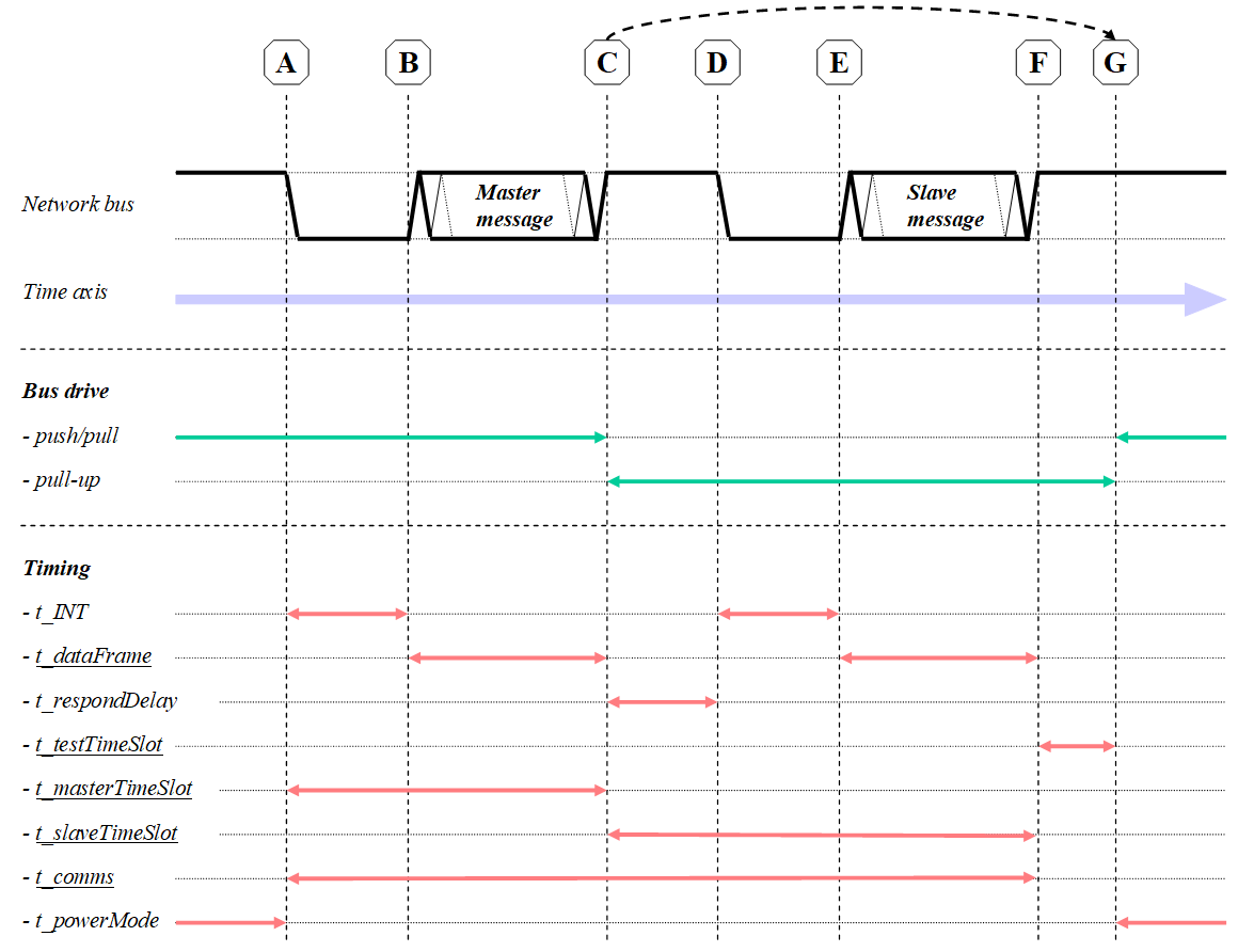
Messaging is initiated by the network voltage level going low. This generates an interrupt at all nodes, making them listen for a message. The master node always initiates the first message. In case this message indicates an available timeslot the corresponding slave process may react with a message in the same fashion (and which is picked up by all other nodes as well). This protocol and its bus state and timing details is shown here:
Highlights
- The master node is completely application-independent.
- Any process on a node can exchange information with any process on another node (including slave-slave comms). Message collissions are avoided by the master node assigning and handing out each sending process a separate ID-marked timeslot.
- Processes/nodes communicate in a loosely-coupled fashion: a process may put a message on the network, all other nodes listen and may react (or ignore).
- After network power-up, the master node automatically roams the network for processes that may want to send messages, and stores the corresponding process IDs for automatic timeslot generation later on. Furthermore, processes can register or remove timeslots for other processes on the fly as well.
- A variant of the network software is also available for simple one-wire "diode-mixing" networks with separate power and serial communication lines.
- At 8MHz a maximum throughput of over 20 messages per second (equals 40 bytes of information) can be reached, the master node may command higher networks speed though. Higher data speeds are supported at 16Mhz or 32MHz clock frequencies.
Hardware
The network supports two variants regarding the electrical design:
- A true two-wire network where both power and serial data is passed, using two interchangeable wires.
- A very simple three wire diode-mixing network with separate power and communication wires.
Learn HERE which network hardware configurations are possible and how they work.
Both SerialPower I and II platforms run on the same hardware.
Software
A separate page is available that describes a number of examples as well as the bare network stacks for both the master and a slave node. All information can be found via the following links:
- Software examples and network stacks for SerialPower I.
- Software examples and network stacks for SerialPower II.
How to start building applications
Application building using SerialPower is easy!
Although the networking software is quite large in size, most of it is application-independent and automates the main tasks, like network message construction from user data, message reception and transmitting. Thus rapid application development is supported.
- What you provide: -
You program the basic functionality of one or more processes in the main body loop of a slave node. Furthermore you give your processes a certain ID (byte) and make these IDs known to the network stack at a certain location. Sometimes you may add code to let other processes pass parameters to the slave process. Finally, your process may write data to a dedicated set of memory locations which will be automatically processed into a network message and transmitted.
- What is already done fore you: -
Basically all required network functionality is implemented in a fully automatic way. This includes network speed determination and automatic timeslot registration at start-up by the master node. Incoming network message handling is performed and may lead to user handling routines being called. Furthermore the network stack inspects whether new data needs to be processed into a network message and subsequently sent at the proper timeslot. Finally a number of helper routines are include to allow slave node user processes to synchronize with the network.
- Steps for a newcomer: -
1. Read Chapters 1 - 7 of the architecture document (see right pane).
2. Then carefully read the User Guide (Chapter 11).
3. Go to the Software Examples section of this website (see above, or in the panel on the right). Furthermore do a file compare of examples S1 and T2 (WinMerge is an excellent program to do this); this will reveal immediately which part of the slave node software is application dependent and which parts are not.
4. Implement your application on your hardware (do not forget to set the proper slave node configuration for the network type you use. This should be done in the slave's User Programmable Area 2).
That's all! Further detail and reference can be found in the architecture document. I am also willing to help, but please post your question/issue on the Picaxe Forum SerialPower thread so that others may help and get informed too.
Copyright
This work is licensed under the Creative Commons
Attribution-Noncommercial-Share Alike 4.0 license in order to support non-commercial, public-domain applications, and to allow application builders to take intellectual ownership of their derived work as well:

To view a copy of this license, you may press on the logo. or send a letter to
Creative Commons,
171 Second Street, Suite 300,
San Francisco, California, 94105, USA.
In short form (me, my = holder of copyright):
- You may use, adapt, and distribute this work
- You must give credit to me when using this code in your application
- If you use my code commercially, I want my share
- You may share your adapted code (now with you as holder of copyright) on the condition that the same license conditions are applied
In order to acknowledge Jurjen Kranenborg (i.e. not the copyright holder of any derived work) as the architect of the original network concepts, I would highly appreciate that you include the following (or similar) statement in all derived works (code, webpages, docs, etc.):
The SerialPower network architecture was originally developed by Jurjen Kranenborg.
About PICAXE™
PICAXE® products are developed and distributed by Revolution Education Ltd
Unit 2 Bath Business Park, Foxcote Ave, Bath, BA2 8SF, UK. PICAXE® is a registered trademark licensed by Microchip Technology Inc.
Contact: jurjen CURLY_A kranenborg PUNKT org
SerialPower Links ...
- Architecture description -
A full, detailed description of the network concept (SerialPower I only) can be found in the
SerialPower Architecture PDF , which includes a User Guide for application development.
- Built by others ... -
- Chuck Bigham's research network
- Other ...
- Hardware -
A description of the three possible network hardware configurations is presented at the hardware configuration page
- Examples page -
Tested example software (as well as the basic master and slave network stacks) can be found via the following software links
- SerialPower I
- SerialPower II
- @ PICAXE Forum -
Main entry on the Picaxe Forum regarding SerialPower (in "User Projects - Communication") which contains a detailed discussion on the message comcept used and its interpretation.
- @ SerialPower I & II Home -
- This is the link towards the Homepage of the SerialPower site.