PICAXE™ "SerialPower I & II" Hardware Configurations
"Combining power delivery and
bi-directional communications between intelligent nodes
using just two interchangeable wires"
The information in this page applies to both:
SerialPower 1 v4.0 for Picaxe M2/X2
(September 2018)
SerialPower II for Picaxe M2/X2
(November 2022)
Summary
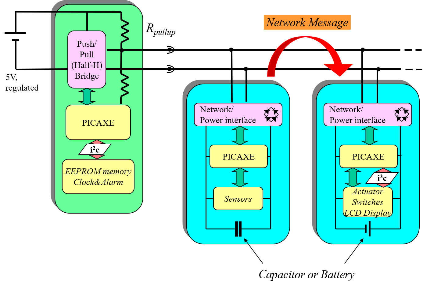
The Picaxe "SerialPower" Network combines power delivery and
bi-directional communications between processes on intelligent nodes. The hardware part of this network may be implemented in two different ways:
- Advanced and flexible: Using just two interchangeable wires that carry both data and power.
- Simple 3-wire: Diode-mixing networks with separate power and communication wires.
This section introduces the hardware design. It presents the main aspects of selecting and refining the design of the proper hardware based on the choice between the beforementioned network implementations. For all technical details please refer to SerialPower Architecture PDF document.
In SerialPower I, the hardware network option is to be specified in the code of the slave node. In the (newer) SeriaPower II implementation, the option is to be indicated in a separate comfiguration file.
True two-wire network (Power + Data combined)
Advantages:
- The simplest possible networking method: two wires (without polarization), implying a very cheap solution. Even an old-fashioned existing wire pair (for example a telephone wire in a house) may be used.
- Extreme flexibility in modular design of applications is possible since the interface is physically simple and does not have a polarization. This means that simple contacts are possible in many ways as an integrated part of the product's physical design, for example using simple plugs, simple contacts using magnets, springs etc. etc..
- The network can be easily incorporated as part of modular, 3D-printed designs.
- Power can be managed at one single point, so no batteries at local modules need to be monitored or replaced since nodes need a back-up capacitor only. Still, a battery can be used in case of a power-hungry node.
Challenges:
- Preferrably use twisted-pair cable in order to minimize interference due to EM-noise.
- The electrical design becomes more complex as compared to the simple three-wire solution due to the power+data interface circuit.
- The power+data interface circuit leads to a lower effective Vcc at the nodes, the node's electrical design needs to accomodate that.
The electrical circuits that correspond to this solution are presented here. Please consult the SerialPower Architecture PDF document for details. Additionally, the following link provides additionl information on why the FVR + comparator solution has been used in the Master Node:
SerialPower: updated implementation for M2/X2 Picaxes .
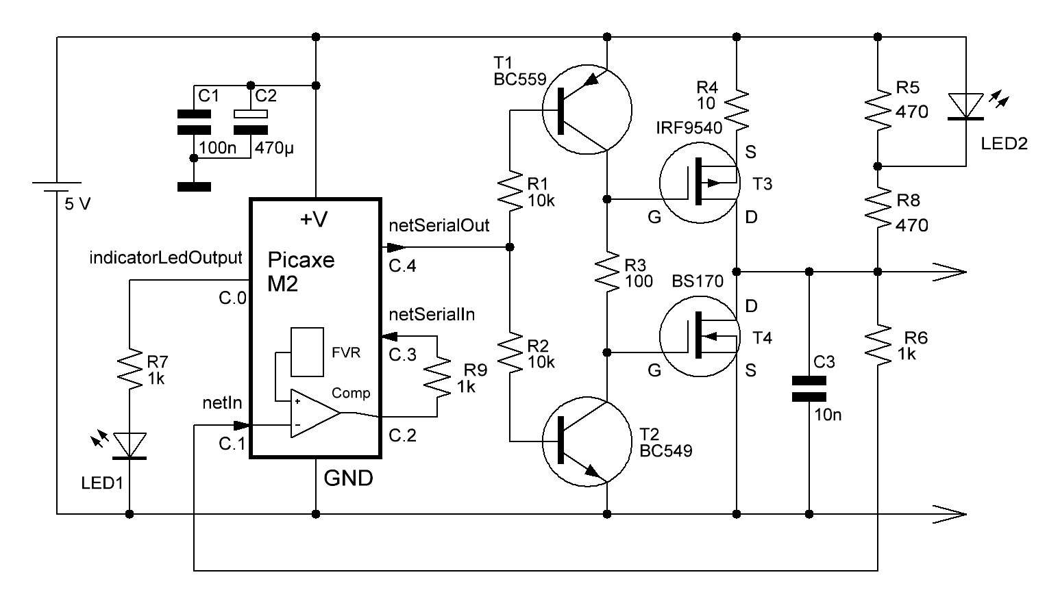
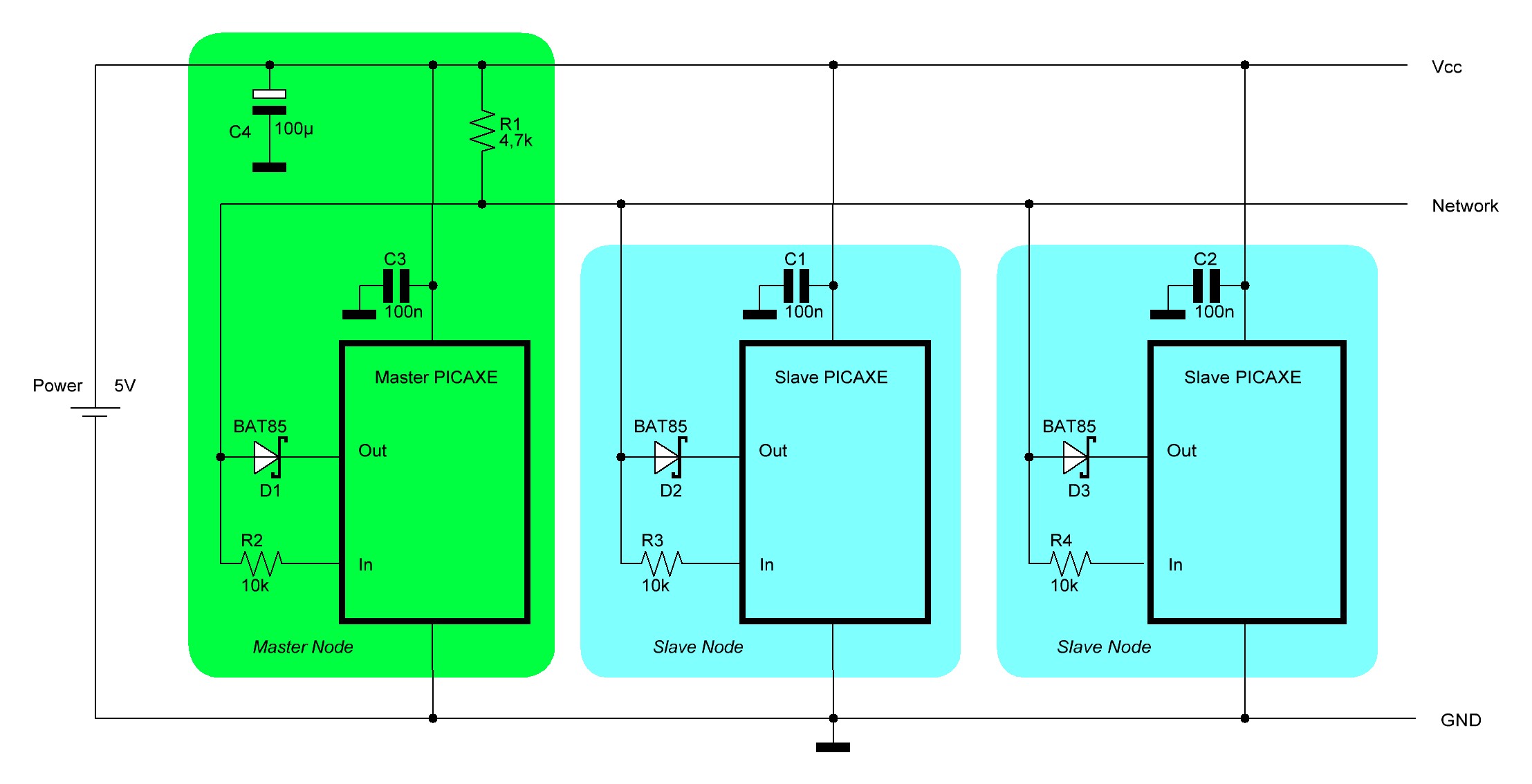
Non-polarized network circuits (Master, Slave):
Master Node circuit:
Slave Node circuit:
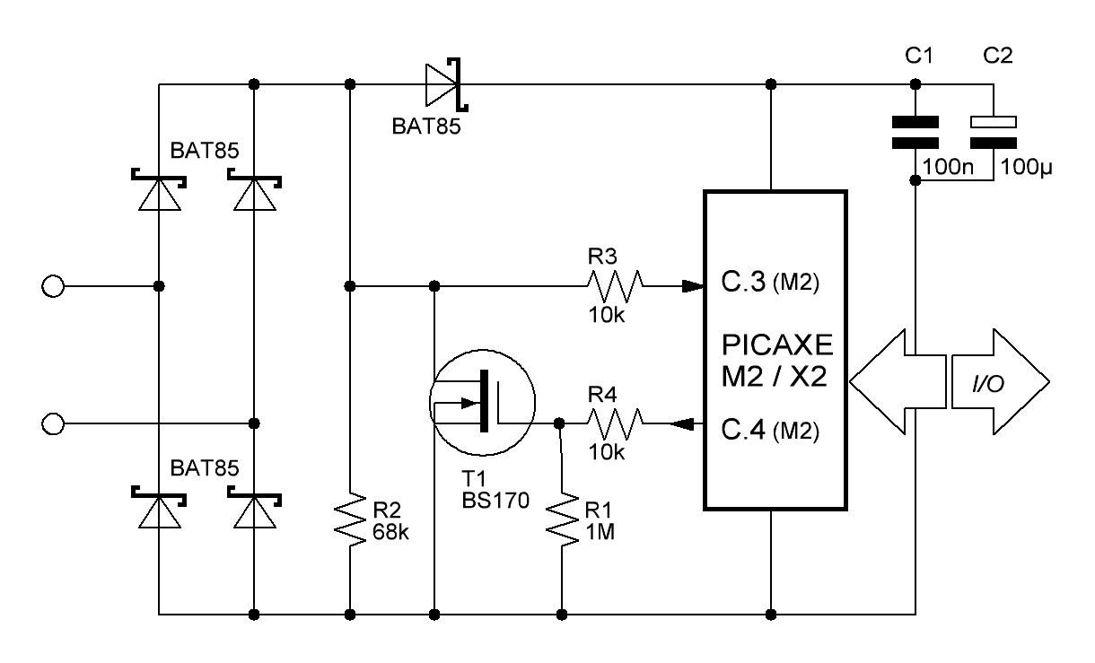
Polarized circuit (Slave):
In case the polarization of the two-wire connection is known (i.e. which wire is connected to the ground line of the Master node), it is possible to considerably simplify the data+power interface of the slave node, as shown here below. An added advantage is that the effective Vcc of the slave node is higher than that of the nonpolarized slave node.
Three-wire simple diode-mixing network (Separate power and Data lines)
Advantages:
- Extremely simple circuit design, requiring only one resistor and diode at the slave node side. Its simplicity implies ease of implementation and testing and low chance of hardware-related errors.
- Perfect for simple prototypeing hardware when developing SerialPower software applications.
Challenges:
- Due to polarized three-wire connection a physical interface between nodes/modules will require a static, physical connector with three contacts.
- Cable shielding for EM-induced moise is more involved than the shielding approach of the two-wire network cable (like twisted-pair).
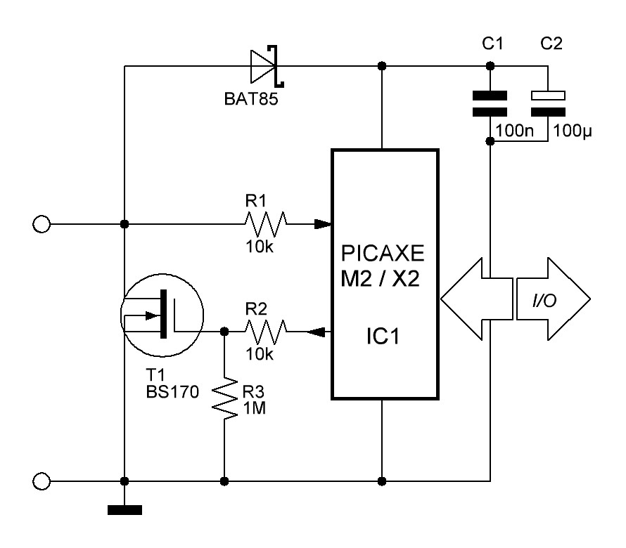
Three-wire network circuit (Master + Slaves):
The electrical circuit that correspond to a three-wire network comprising both Master node and Slave nodes are presented here. Please consult the SerialPower Architecture PDF document for details.
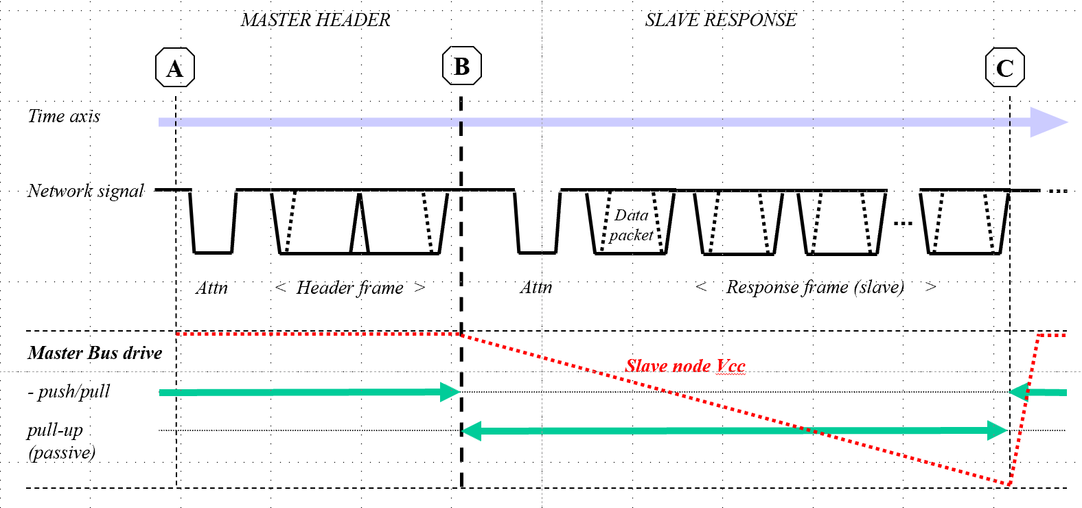
SerialPower II: How APP (Active Power Provision) works for a two-wire network
In SerialPower II, relatively long messages are possible. In case of a slave node transmitting on a two-wire network, the network is in weak pullup mode and therefore any slave node on it does not receive signicant power. As a potential consequece, the node may "die" when sending a long message (the red graph indicating the Slave Node Vcc level) if no additional measures were taken:
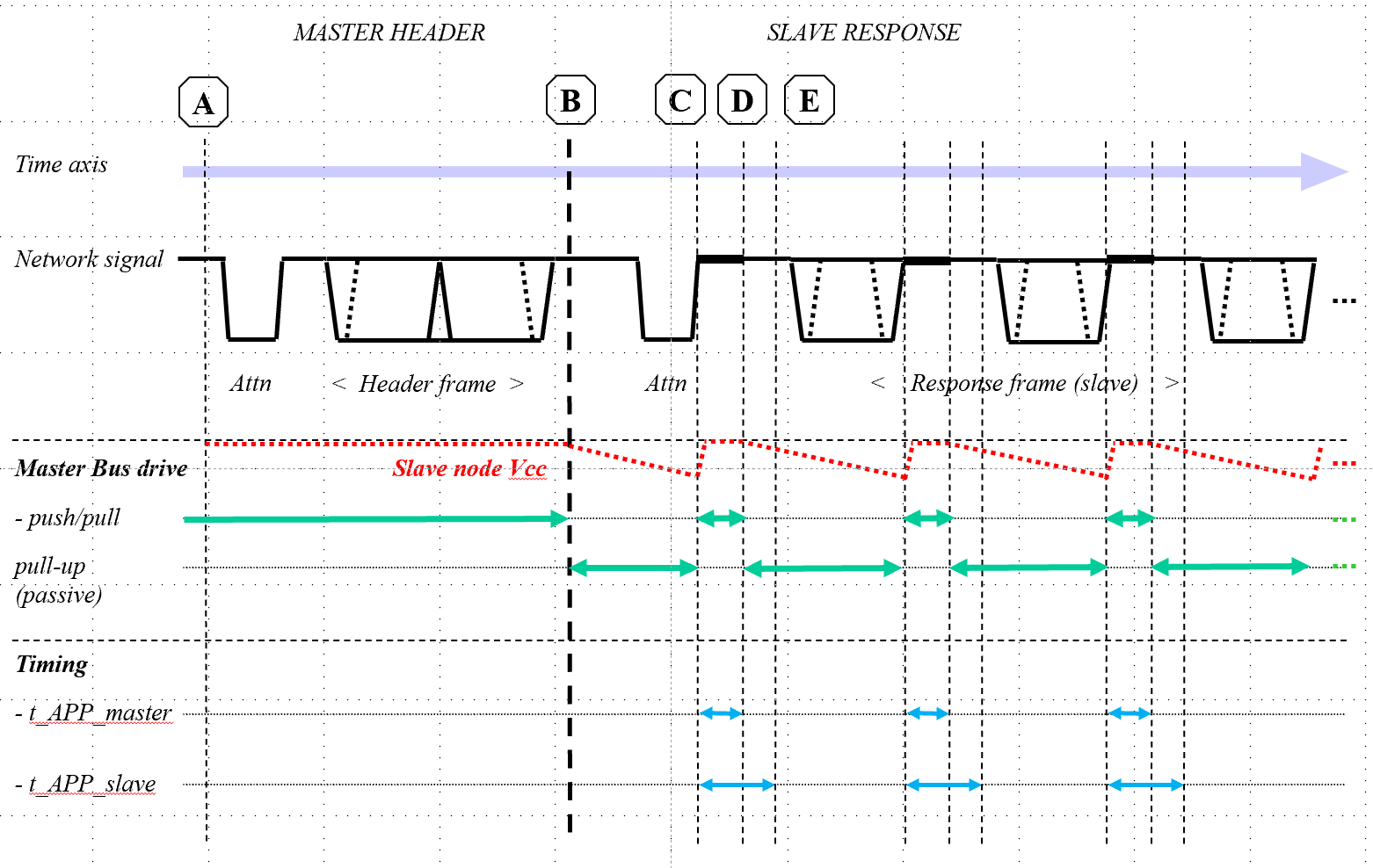
With APP, a short active power period is added directly after each byte transferred. As a consequence, all slave nodes are re-charched each time and their local power level only has minor fluctuations, as shown schematically here:
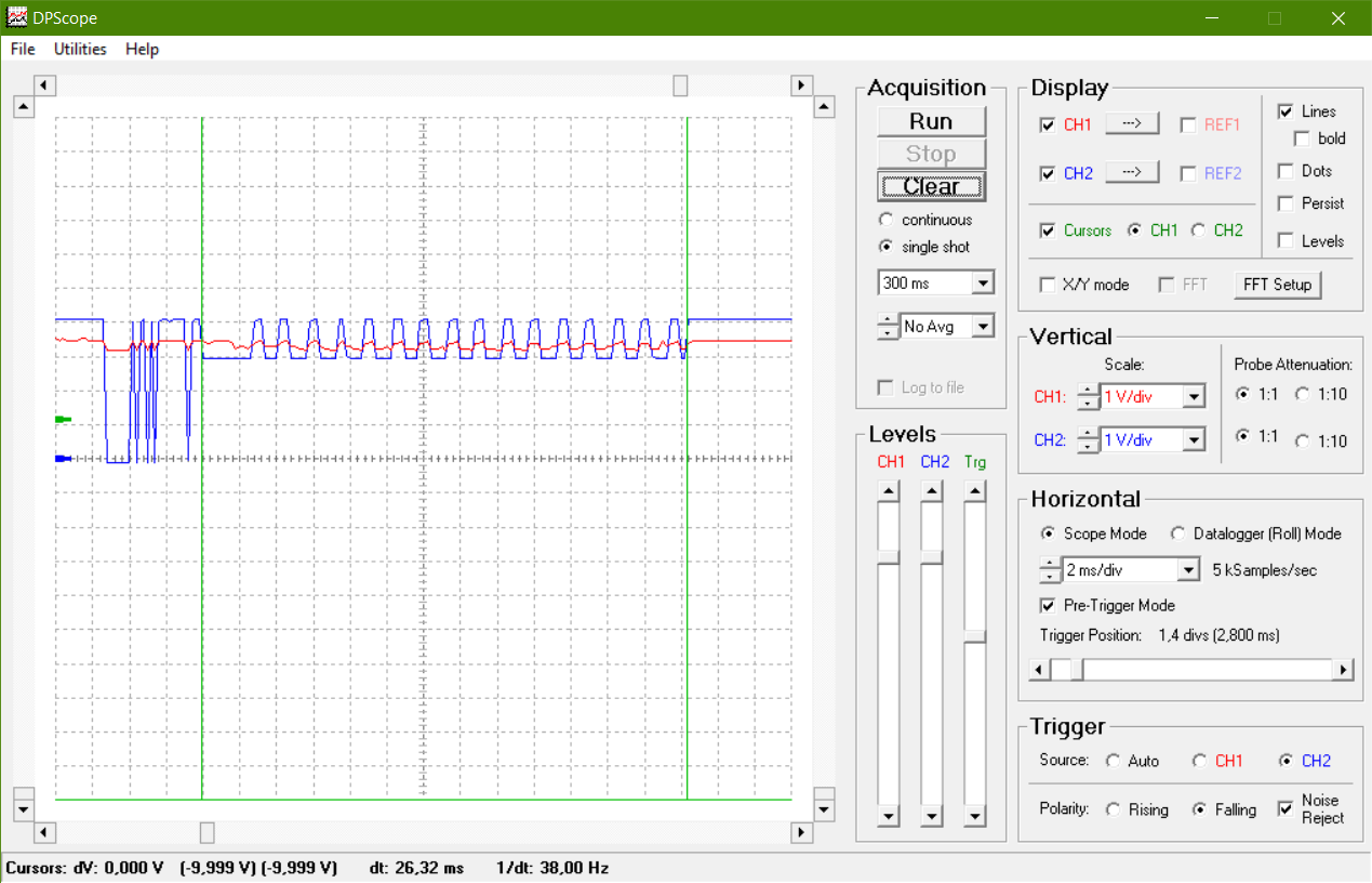
As a concrete example, here is a scope view of the "Hello World" transaction by a slave node for the case where no APP is applied (Red graph: Local Slave Node Vcc, blue graph: Master Node output port voltage level, indicating the three-state output levels). The Slave node's voltage is clearly sagging, and after completion of the message transmission some time (and significant current) is needed to recharge:
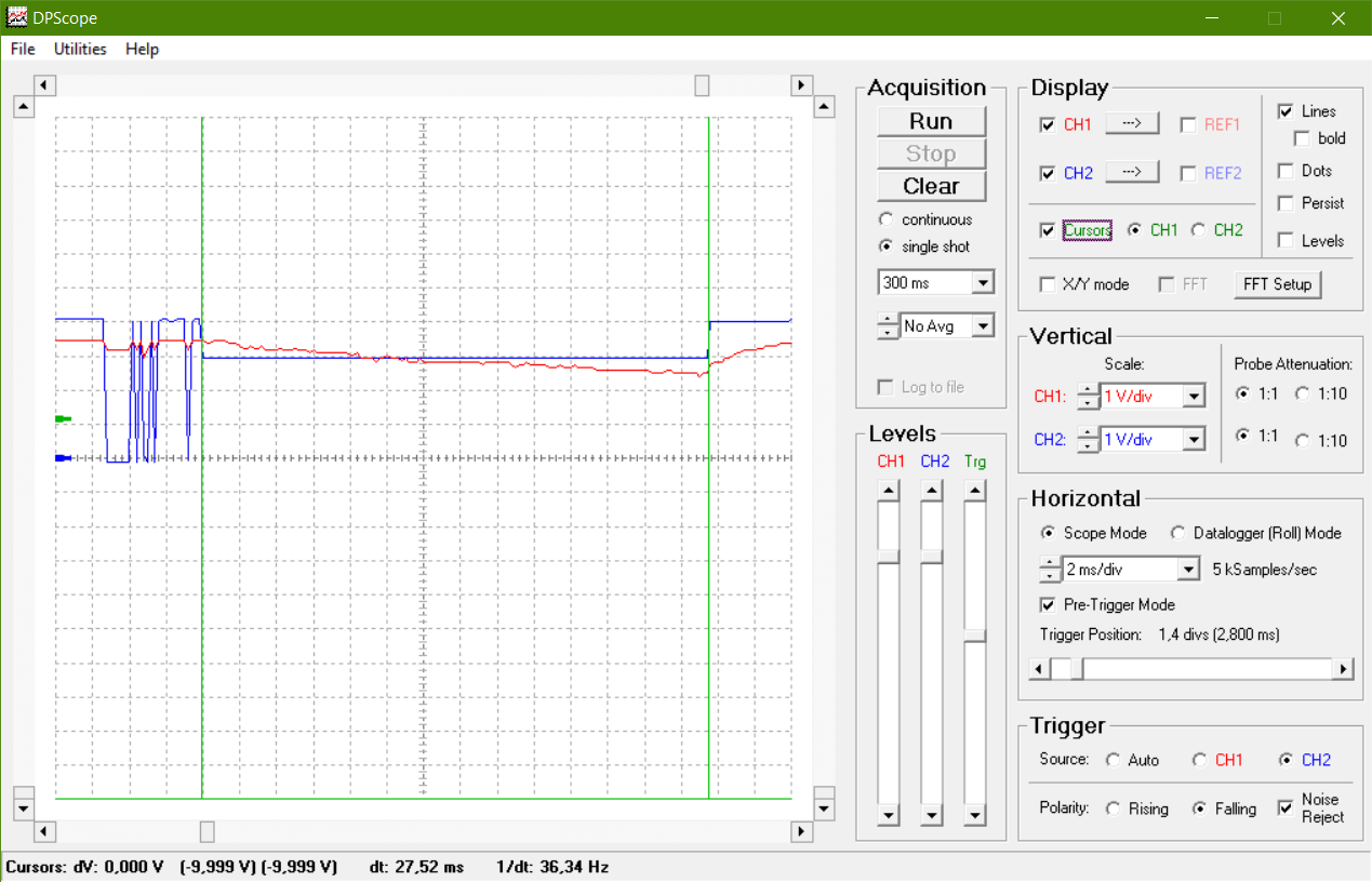
... and here is the case where APP has been selected (through the configuration file), showing that the slave node Vcc remains at a safe level thoughout the message transmission:
Copyright
This work is licensed under the Creative Commons
Attribution-Noncommercial-Share Alike 4.0 license in order to support non-commercial, public-domain applications, and to allow application builders to take intellectual ownership of their derived work as well:

To view a copy of this license, you may press on the logo. or send a letter to
Creative Commons,
171 Second Street, Suite 300,
San Francisco, California, 94105, USA.
In short form (me, my = holder of copyright):
- You may use, adapt, and distribute this work
- You must give credit to me when using this code in your application
- If you use my code commercially, I want my share
- You may share your adapted code (now with you as holder of copyright) on the condition that the same license conditions are applied
In order to acknowledge Jurjen Kranenborg (i.e. not the copyright holder of any derived work) as the architect of the original network concepts, I would highly appreciate that you include the following (or similar) statement in all derived works (code, webpages, docs, etc.):
The SerialPower network architecture was originally developed by Jurjen Kranenborg.
About PICAXE™
PICAXE® products are developed and distributed by Revolution Education Ltd
Unit 2 Bath Business Park, Foxcote Ave, Bath, BA2 8SF, UK. PICAXE® is a registered trademark licensed by Microchip Technology Inc.
Contact: jurjen CURLY_A kranenborg PUNKT org
SerialPower Links ...
- Architecture description -
A full, detailed description of the network concept (SerialPower I only) can be found in the
SerialPower Architecture PDF , which includes a User Guide for application development.
- Built by others ... -
- Chuck Bigham's research network
- Other ...
- Hardware -
A description of the three possible network hardware configurations is presented at the hardware configuration page
- Examples page -
Tested example software (as well as the basic master and slave network stacks) can be found via the following software links
- SerialPower I
- SerialPower II
- @ PICAXE Forum -
Main entry on the Picaxe Forum regarding SerialPower (in "User Projects - Communication") which contains a detailed discussion on the message comcept used and its interpretation.
- @ SerialPower I & II Home -
- This is the link towards the Homepage of the SerialPower site.