The EE2016 Ultrasonic converter circuit needs only some minor tweaks to turn it into a very useful bat detector. Furthermore, the circuit has several interesting aspects that are not covered in the manual and therefore warrants a separate discussion. The picture below is my implementation and it is discussed here in detail.
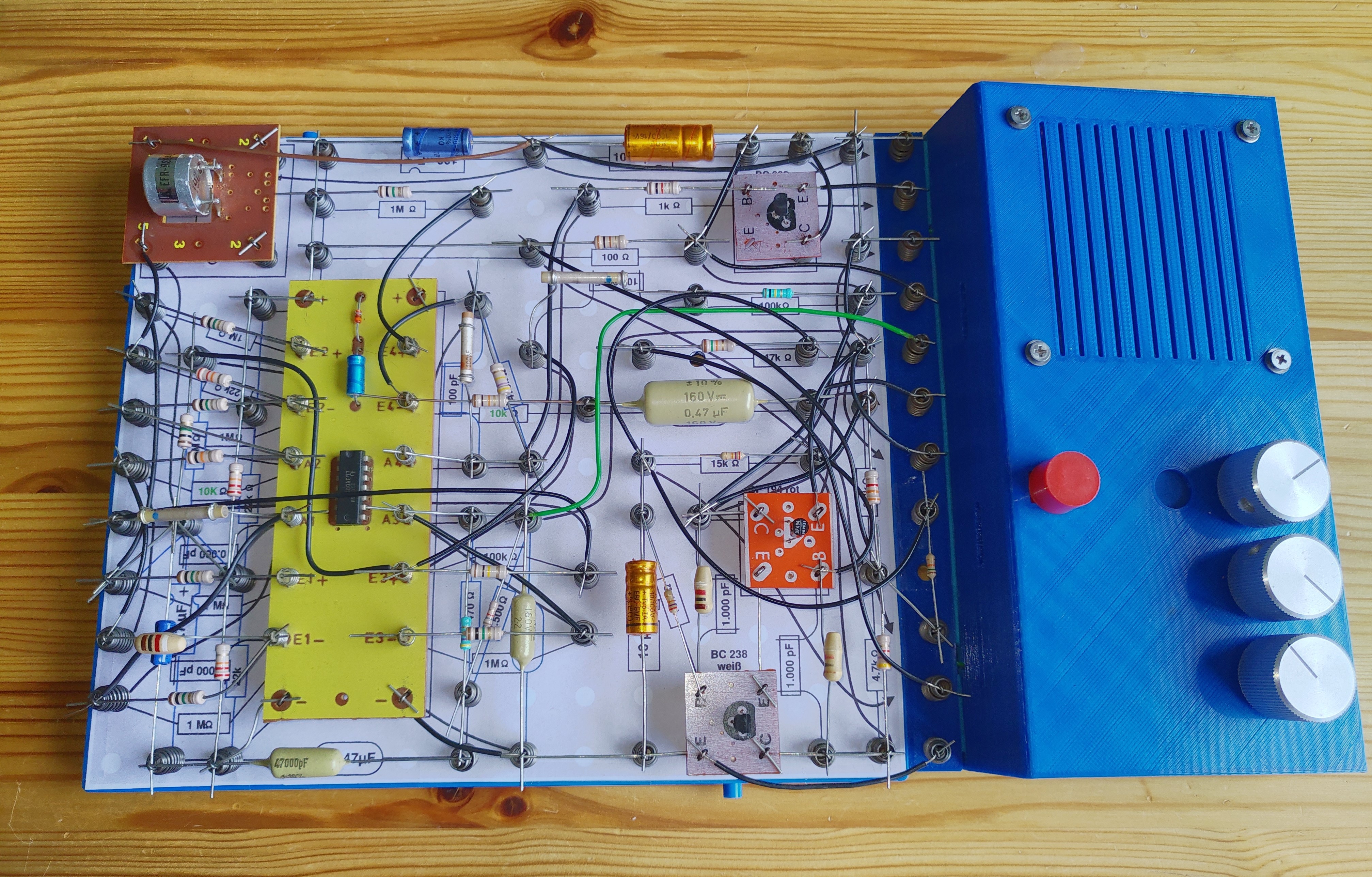
This bat detector circuit is based on the original EE2016 4.7.14 circuit ("Ultraschall-Konverter" - Ultrasonic Converter), with the following small but meaningful improvements:
- Compact layout design made for one Philips EE board instead of the original two boards, as shown above
- Improved oscillator circuit (T1/T2),
- Increased sensitivity by reducing a few resistors values, and
- Large capacitor added in the Vcc line for better stability.
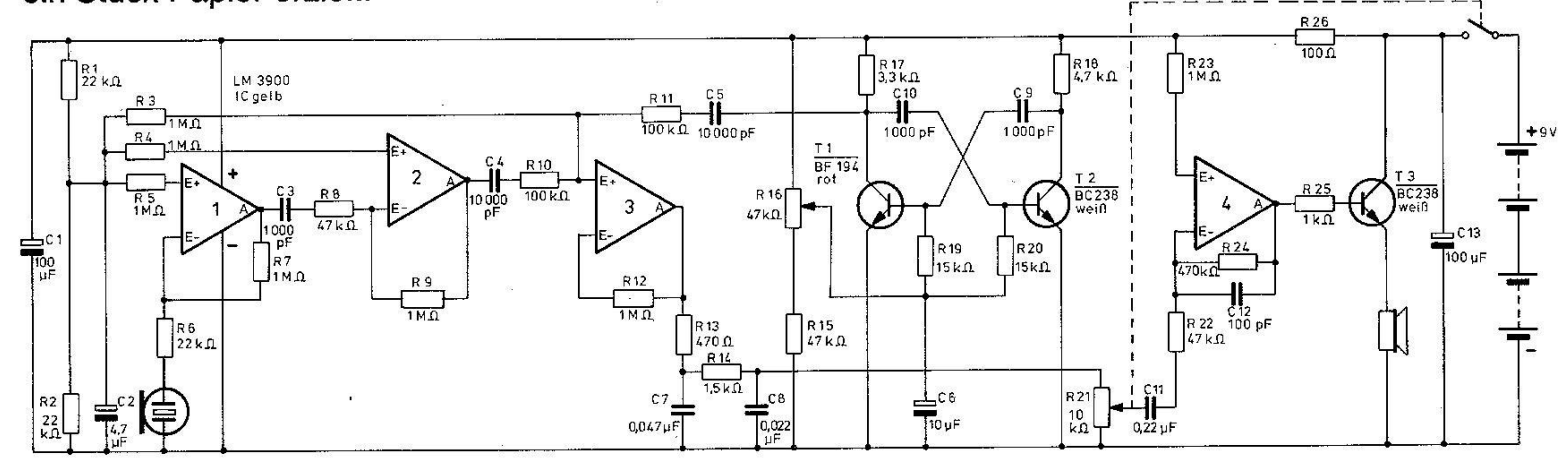
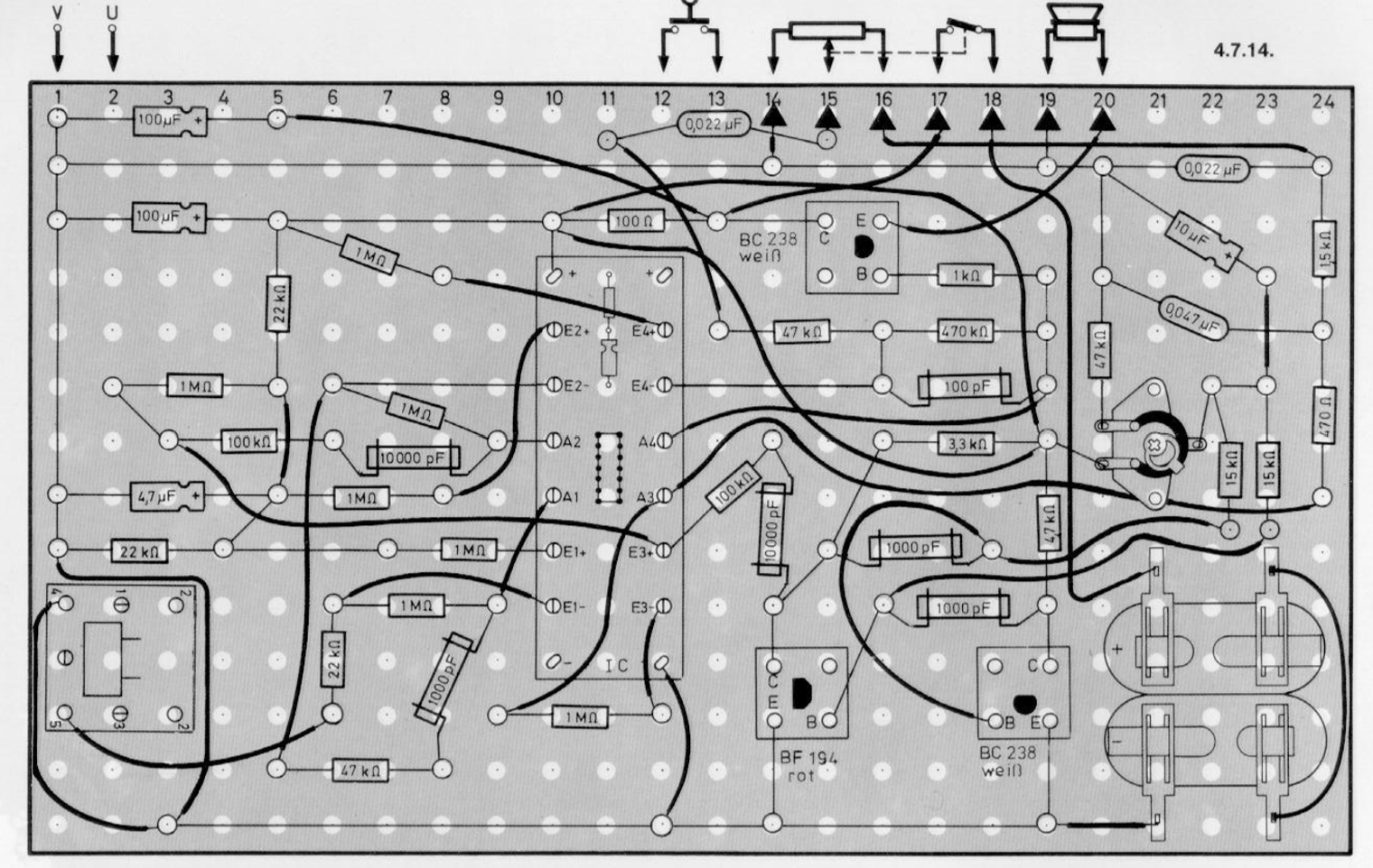
The original electronic circuit and component layout in the Philips EE manual are as shown in the figures here below:
The new design appears to work very well: a recording that I made with it is available here: Audio link
It is based on the following improvements:
Compact layout:
The motivation for a more compact version of the layout - aiming for one EE-board - is that it can be more easily used practically used and carried around as an ultrasonic bat detector, as a specific but very suitable and fun application of the ultrasonic converter.
Using Tor Gjerde's Philips EE template files and WinFig (winfig.org) I was able to fit the new layout om a single board as follows:

The connections to the 3D-printed console then should be as follows (from top to bottom):
- Speaker (+)
- Speaker (-)
- GND
- Vcc (Between 9V - optimal - and 5V)
- 10k Volume control pot (log), "hot" end
- 10k Volume control pot (log), middle, variable
- 10k Volume control pot (log), mass (GND)
- n.c.
- n.c.
- 47 Freq control pot (linear), "hot" end
- 47k Freq. control pot (linear), middle, variable
- 47k Freq. control pot (linear), mass (GND)
The layout files are available here:
- WinFig (Xfig) version: link (.fig)
- PDF version: link (.pdf)
Improved oscillator circuit:
The unstable multivibrator around T1/T2 (see the original EE2016 circuit) with frequency adjustment is not so stable in the EE2016 original circuit 4.7.14 (ultrasonic converter). The applied circuit - using only one potentiometer for setting the base voltage - is also used in other Philips circuits, e.g. Ee2004/5/6 (2.09, 4.29, 7.03, 7.04) and EE2017 2.57.
For a perfect frequency control, a "double-ganged" potentiometer would actually be needed ( link ) , a setup that can even be built with the old EE1004 (with two potmeters and included extension ächse), but this does not go without effort into the EE200/2001 series ... .
The problem with the original circuit 4.7.14 with only one potentiometer (R16) is related to the relatively low values of R19/R20, which can cause an unwanted coupling at the base between T1 and T2 with certain setting of R16. The proposed circuit below seems to solve this problem satisfactorily and proves to be very stable and controllable (but has a slightly lower frequency range compared to the original).

In addition to an increase in the values of R19/R20 (15k -> 27k), a direct coupling to the (+) is also added to guarantee a satisfactory base voltage for T1/T2, because ultimately R15 (47k -> 15k) is in a better place to achieve a good frequency range.
Increasing sensitivity - Changing some resistance values
Compared to the original EE2016 design, the following resistances have been lowered to increase the amplification of the circuit without jeoparding its stability:
- R8: 47k -> 10k
- R22: 47k -> 10k
Large capacitor added in the Vcc line for better stability:
To guantee the stability of the circuit even at high audio volumes, the following change was made:
- C13: 100uF -> 680uF (or larger)
Acknowledgements:
The redesign and use of this circuit has benefitted greatly from discussions on Rigert's Philips EE forum, see the following thread: Forum link