Information and Enhancements/Corrections on the
Philips EE2000/EE2001 series
Keywords: Philips EE kits, EE2000 series, EE2001 series,
LM3900, EE2005 superhets, IF Coil data
This page presents additional information sources and/or
enhancements/corrections based on my personal experiences. Please
respond if you have (other) improvements or information sources
as well.
EE2000 Series (applies also to EE1000 and EE3000
series)
1.1 (EE2003/4/5/6) Suggested redesign
of two-transistor audio amplifier stages
In many constructions a two-stage audio amplifier is used to
drive a loudspeaker. In almost all cases (for example the EE2003
medium wave receiver 5.02, the only exception is the 5.03 SW
receiver) a design is used in which the 10K potentiometer (volume
control) drives two subsequent BC238 transistor stages, the
latter tied together directly via a 4.7uF or 10uF elco. This
approach has the following drawbacks:
- As the potentiometers age, more and more noisy
disturbances are produced when turning the potentiometer.
With two subsequent amplifier stages these disturbances
are amplified many times as well, resulting in a low-quality
audio output when changing the volume.
- In the EE2005 superhet receivers the performance of the
diode detector part is degraded severely by the fact that
the volume control is applied after the detector part,
probably due to the fact that the loading of the detector
circuit changes when adjusting the volume.
A better approach is to change the location of the volume
control in the circuits; the 10K potentiometer should be put in
between the two white transistors instead of before them.
The SW receiver on this website shows such a configuration, as
well as the way to couple the audio circuit with a preceding
circuit. I have applied it succesfully to the EE2005 superhets;
it eliminates the disturbances almost completely and provides for
stable operation of the superhet designs.
1.2 (EE2005) Trimming of IF coils
The red transformers in the EE2005 kit contain a small ferrite
bead whose position can be changed by turning it with a small (preferrably
plastic) screwdriver. In this way the coils can be trimmed
towards equal frequency, which is very important for the IF
signal strength applied to the diode detector of the superhet
designs. The best way to trim the transformers is the following
approach:
- Put the beads in the red transformers in approximately
the middle position (so that they can be turned in both
directions)
- Build the superhet receiver, calibrate it using the
directions in the manual and search for a relatively
strong radio station.
- Adjust the second red transformer (the
one closest to the diode detector part, adjust by turning
its ferrite bead) for maximum perfomance
In this way the diode detector get the maximum amount of IF
signal, which is very important for the
operation of the germanium diode detector as it needs a signal of
more than 0.3V to operate properly ( signals with a forward diode
drop of less than 0.3V will not be demodulated at all).
1.3 (EE2005) Better stability,
perfomance and audio quality for the EE2005 superhet receivers
I have seen several reports of disappointing/bad or even
absent performance of the EE2005 superhet receivers, and I
experienced some problems too. I have found the combination of
the following measures to solve all problems:
- Change the audio part (i.e. around the white transistors)
according to point nr 1.1 above. This will
guarantee undisturbed operation of the diode detector
when the volume is changed.
- Trim the red IF transformers according to point nr.1.2
above. This will deliver the maximum signal to the
detector. As a result very weak, remote radio stations
can be received without the use of an antenna. For
example, the performance (sensitivity) of the SW superhet
appeared to be even somewhat better than the redesigned
regenerative SW receiver on this site
- If the MW/LW superhet (or sometimes the 1.7 - 4.0MHz
superhet) tends to oscillate, use a small capacitor (10pF
or smaller) to connect the base of T1 (first red
transistor) to mass (0V). Apparently, the oscillator
produces an additional signal (probably higher harmonics)
that tends to destabilize the receiver; the bypass
capacitor removes this signal directly. Note that the
1978 version of the EE2004/5/6 manual (i.e. the second
edition) shows an extra 1000pf ceramic capacitor in
parallel with the electrolytic capacitor that stabilizes
the T1 supply voltage. This ceramic capacitor serves the
same purpose; apparently it was recognized by the circuit
designers that the stability of the receiver was
problematic and needed treatment (Tor Gjerdes diagram
of the MW/LW superhet shows the location of the 1000pf
capacitor near the ferrite antenna rod).
- Connect the antenna directly to the point where the main
receiver coil is connected to the variable capacitor. The
original point (at the connection of the coil with the
2700pf capacitor) does not work. Still, with the measures
above an antenna is probably never needed.
- Use two small trimmers (10pF each) on the breadboard
instead of the trimmers on the double variable capacitor.
Adjusting these trimmers is extremely important
for good reception, and is much easier to do on
the breadboard. These trimmers can be seen on the 3-IC
superhet on my "New Designs"
page. Without careful trimming the superhets may not
function at all.
- The following trimming policy gave very good results:
First set the receiver at the low frequency region by
turning the tuning dial right (the oscillator trimmer may
be used to change the frequency range a bit). Now the
reception part has to be adapted to the oscillator.
Firstly change the position of the receiver coil for
optimal reception of a radio station. Now turn the tuning
dial to the left (high frequency area), search for a (weak)
radio station and only use the other (reception
circuit) trimmer for optimal performance.
- Short-Wave superhet: This design has a frequency range of
4 to 10 MHz. However, the 4 to 5.5 MHz range is not very
interesting, so it is appropriate to limit the frequency
range a bit by including two 470pF ceramic capacitors in
series with the double variable tuning capacitor (or use
an even smaller value, like 330pF of 220pF).
- The 1.8 - 4 MHz superhet and the 80m amateur band
converter (3.5 - 4 MHz) are not very interesting designs
anymore, as virtually all communications on these
frequencies have shifted from AM mode to SSB mode. The 80m
version of the regenerative SW receiver mentioned on my
"New
Designs" page is an interesting alternative
design for this frequency range, as it provides for both
AM and SSB reception modes.
1.4 (EE2005 2nd version with new,
modern coils [applies also to EE3004, EE2000GK]) IF and OSC
Coil Data
At the end of the lifetime of the EE2000 series the EE2005
coils types that were already present in the EE1000 series (and
were tailor-made by Philips for the EE series) were replaced by
modern types. The manual update leaflet included in the kit does
not specify any technical information on these coils. A variety
of IF and oscillator coils currently exists on the market, and
here I try to explain the differences between them and provide
some technical data that I am confident of and which seems to
apply to the coils in the Philips EE kits:
- In contrast to the old (red) IF coils, the two new
IF coils are technically different. The
reason for the differences between the modern white resp.
black IF coils is that these coils are specifically
designed for the very popular and cheap standard
transistor radio architecture of the seventies. This
architecture defines a combined oscilllator/mixer
transistor stage followed (through coupling by a first,
yellow IF transformer) by the first IF transistor
amplifier, followed (through a second white IF
transformer) by a second IF transistor amplifier stage,
which is then followed (through a third, black IF
transformer) by a diode detector. Each of the stages has
different impedance characteristics, which implies that
each IF transformer needs different coil windings in
order to match these impendances for optimal performance.
The EE2005 superhets largely follows this architecture (and
they even include a rudimentary AGC action), but contain
only the second IF amplifier stage (which explains why
the first, yellow IF transformer is absent in the EE kits.
I have the impression that weak regeneration in the
second IF stage is used to increase IF gain as a
compensation of the absent IF amplifier).
- Even for each IF transformer type (i.e white and black)
several versions exist (see www.mouser.com for an
overview), but the differences are small (mostly wrt. the
number of coil windings) and are not very relevant. The
following data common to these versions can be
established and most probably characterize the two IF
coils present in the EE kits very well:
| IF type (color) |
Primary impedance (Ohm) |
Secondary impedance (Ohm) |
Unloaded Q |
Internal capacitor. (pF) |
Inductance (uH) |
Probable Mouser type numbers |
| white |
30K |
500 |
80 +/- 20% |
180 + 5 (ext.) |
680 |
42IF102, 42IF302 |
| black |
20K |
6K |
75 +/- 20% |
180 + 5 (ext.) |
680 |
42IF103, 42IF303 |
- I have no clue to where the tapping of the primary coil
is actually located, so therefore information on the
number of turns is not presented.
- The internal capacitor (180 pF) causes the IF
transformers to be fixed at 455KHz, in contrast to the
old versions where the capacitor is external and is made
parallel to the coil by explicit wiring, thus allowing
different frequencies.
- The orange AM oscillator coil
most probably has the following characteristics (with
differences between various types in the number of turns
but not in the center frequency or inductance, but I have
no clue to which option applies to the Philips EE
component version, and therefore I present the values of
a particular coil type (Mouser 42IF110). Note that the
tap numbers mentioned in the rightmost column of the
table are corresponding to the Philips EE circuit
diagrams, not the Mouser diagrams:
| Center frequency |
Primary (oscillator) inductance |
Unloaded (primary) Q |
Turns (primary 4-5-6 and
secondary 1-2) |
| 796 KHz |
360 uH |
80 |
4-5: 105, 5-6: 2, 1-2:
3 (typical) |
- I was not successful in retrieving any data for the blue
SW coil. The metal coil housing bears the
mark SW (for "Short Wave") on the side, and the
name "Yocom" on the top, but this did not help
in identifying any information. Currently I have the
impression that this coil is of special design. To
retrieve more information the use of an LC-meter would be
appropriate here. Also some information may be derived
from the circuit diagram for the SW receivers (in
particular the coil inductance). Note also that the SW
oscillator coil is not tapped (the secondary is), as
opposed to the AM oscillator coil, and this explains the
differences bweteen the schematics of the AM and SW
superhets.
1.5 (EE2005 2nd version with new,
modern coils [applies also to EE3004, EE2000GK]) Errors/deficiencies
in manual update leaflet
In the kits that contain the new type of coils a leaflet is
included that describes some updates of the original EE2005
circuit diagrams that use these coils, and some extensions of the
various receivers. However the leaflet contains some flaws, and
does not provide any technical data on these coils (but see item
1.4 above on this matter). Here I present some information and
updates:
- The schematics contain some errors:
- For the IF transformers the internal capacitors
between taps 4 and 6 are not shown.
- In some diagrams the feedback line (containing a
22nF capacitor and 10 Ohm resistor) between tap 6
and the emitter of T1 is not drawn.
- Schematics 5.10 and 5.11 should be reversed
- I have the impression that all construction diagrams are
correct though.
- The superhet construction diagrams are drawn quite
different from the original versions and (at least to my
impression) may require the bending of many components. I
would rather recommend to use the original superhet
construction diagrams in the EE2004/5/6 manual and just
replace the old coils and rewire the new types.
- The explanation of the 5.10 SW superhet pertains to the
original version with the old type of coils. The new
construction does not use the first harmonic of the AM
oscillator coil, but uses the base frequency of the SW
oscillator coil that has been included in the new kit
versions.
- I do not think that the fine tuning option for the SW
receiver (5.11) works well, as I have experienced that
the narrow 455KHz IF frequency filtering causes the
system to get detuned very quickly. I have the impression
that fine tuning is not needed anyway as the tuning knob
is large and allows for quite precise frequency
adjustment.
- Use the suggestions of item 1.2 for trimming the IF coils.
After careful trimming they should not be adjusted (separately)
again (as suggested in the leaflet), as this will
severely degrade both selectivity and sensitivity due to
a mismatch between their resonant frequencies.
EE2001 Series
2.1 Information on the LM3900 Norton
OpAmp
In the EE2001 series constructions the LM3900 plays a central
role. It is quite an old chip (released in 1972 by National
Semiconductor, still in production by Texas Instruments); in fact
is was the first chip that provided four opamp gates on a single
chip, which was possible because of the relative simplicity of
the gates when compared to the "de facto standard" 741
opamp. Since internet access has almost become a commodity we now
have the opportunity to have access to this well-documented chip.
Here follow links to the LM3900 Data Sheet containing electrical
characteristics, and the important AN-72 Application Note (43
pages!) which contains a wealth of basic LM3900 circuits (some
interesting ones are not in the EE2010/13 manual).
It is important to stress that the LM3900 is not a
regular quad opamp: instead of Vout = A*(Vin+ - Vin-) (which is
what a regular opamp does; the output voltage equals A times the
voltage difference between the +/- input terminals) the LM3900
basically delivers Vout = A*(Iin+ - Iin-), i.e. the output voltage
equals A times the input current difference between the
+/- inputs. As a consequence the LM3900 as low-impedance inputs,
in contrast to regular opamps which should have high-impedance
inputs. However, in the EE2001 series manuals the LM3900 circuits
are always designed and explained as if the chip contained
regular opamps (see issues 2.2 and
2.3 for the consequences)
For an interesting explanation between regular OpAmps and
"Norton"-type amplifiers like the LM3900 see the
following link (especially chapters 8 and 9 on voltage vs.
current differencing amplifiers):
The LM359: A successor of the LM3900
Although not a pin-compatible replacement, the LM359 is a
successor of the LM3900 with improved technical specifications:
- User programmable gain bandwidth product,
slew rate, input bias current, output stage biasing
current and total device power dissipation
- High gain bandwidth product (ISET
= 0.5 mA) 400 MHz for AV = 10 to 100 30 MHz
for AV = 1
- High slew rate (ISET = 0.5 mA)
60 V/µs for AV = 10 to 100 30 V/µs for AV
= 1
- Current differencing inputs allow high
common-mode input voltages
- Operates from a single 5V to 22V supply
- Large inverting amplifier output swing, 2
mV to VCC - 2V
- Low spot noise, for f > 1 kHz
The LM359 is a dual "programmable" opamp in a 14-pin
package. The two opamps each have two extra input pins for
external frequency compensation. This chip is interesting for
designers who are accustomed to the LM3900 but need a much faster
chip (all LM3900 circuits can be applied with the LM359 too).
Please refer to the following links for detailed information:
2.2 {EE2010/13) Flaws in the
explanation of LM3900 circuits in the EE-manuals
2.3 (EE201X) Starting problems of LM3900
multivibrator circuits
2.4 (EE2015) Powering suggestions
The EE2015 kits contain chips that are implemented in the
original TTL technology. As a result the EE2015 circuits consume
quite some battery power (I didn't measure) and consequently the
batteries get exhausted quite rapidly (which I do remember).
Currently there are a few powering options available:
- Use a 9V supply (i.e. two batteries) in combination with
a 5V Voltage regulator (7805 or equivalent). This is the
simplest solution; it extends the time of use, but
doesn't decrease power consumption
- Exchange the chips for their much less power consuming LS-TTL
(Low-power Schottky) counterparts (i.e. 74LS02 etc.).
This probably is the best solution, as all chips have the
same functionality, and the EE2015 circuits do no need to
be changed.
- Exchange the chips for CMOS versions. This is the best
solution regarding power consumption. However, be aware
of the following issues:
- Not all chips are available in the same CMOS
technology, or even not fabricated in CMOS at all:
there exist 74HC02, 74HC05 (HC series), and 74C90
(CMOS, but not in HC technology). The 7447 is not
available in any CMOS technlogy, so you probably
would use an LS-TTL version (74LS47)
- As CMOS chips have high-impedance inputs, a pull-up
resistor is necessary when connecting an open-collector
output (which is the case for 7405, 74LS05 and 74HC05,
as explained in item 2.5 below)
to a CMOS input. As a result some pull-up
resistors would have to be added to several EE2015
circuits
2.5 (EE2015) Erroneous LED connections
to 7402 outputs
The EE2015 kit uses logic gates which have different output
ports. The 7405 inverter has so-called "open collector"
outputs, which means that the output of this gate merely contains
a switch connected to ground. As a result a pull-up resistor is
needed to drive a device like a led or a transistor, as shown in
the figure below in case (a). Most other gates however (7402,7490)
have active-drive outputs, which means that these outputs
themselves directly drive a device whithout the need for pull-ups,
as shown in case (b).
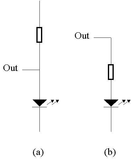
In the EE2015 manual however , concerning all circuits, the
7402 active-drive output circuits are erroneously designed as if
they were open-collector outputs, i.e in fashion (a) instead of (b).
As a result the current flow through the device is limited only
by the output-drive capability of the 7402, not by the protective
resistor in case (b), and this may in the end damage the LED or
other attached device. So, case (b) descibes the correct way of
treating 7402 outputs, whereas case (a) pertains only to 7405
outputs.
Contact me